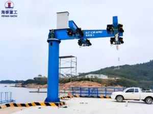


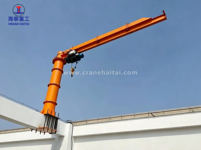
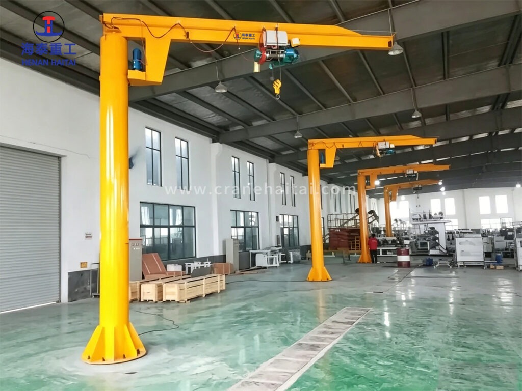
Haitai floor mounted jib crane is a free-standing pillar jib crane anchored directly to the workshop floor via a reinforced concrete foundation. Fitted with an electric chain hoist or wire rope hoist on a motorized trolley, it provides 360° or 270° slewing coverage across a working radius of up to 8m.
Its special structure and flexible rotation makes it the standard lifting solution for dedicated workstations, assembly cells, production lines, and maintenance bays where a full overhead crane is either unavailable or impractical.
Unlike wall-mounted or column-mounted jib cranes, the floor-mounted pillar design imposes no load on building structure. We install it independently of the building frame, so we can position it anywhere on the factory floor and relocate it when the production layout changes. We can position floor-mounted jib cranes at a production machine, a loading dock, a welding bay, and a material transfer point.
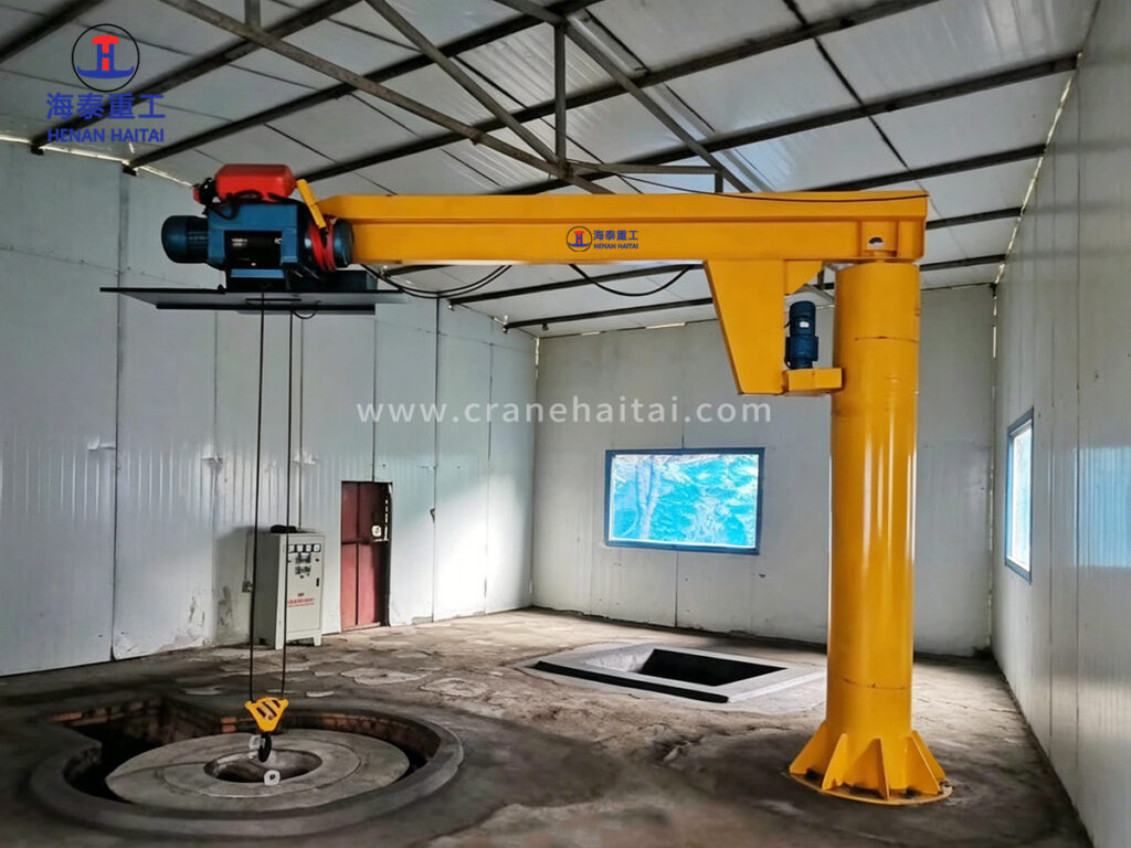
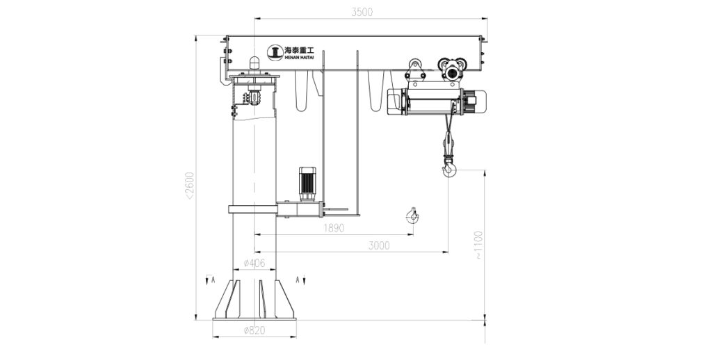
The main column is a structural steel circular hollow section (CHS) manufactured from Q345B plate, rolled and seam-welded to dimensional tolerance. The base flange is a thick-plate machined steel disc full-penetration welded to the column base. Anchor bolt holes are drilled to the foundation drawing pattern. The standard configuration shown in the Haitai engineering drawing uses φ406 mm column OD and φ820 mm base flange — sized for 3t capacity at 3,000 mm working radius. Column height ≤2,600 mm (to jib bottom flange) is the standard range; taller columns require engineering review.
The jib arm (horizontal boom) is a welded box section or I-beam fabricated from Q345B structural steel. The arm connects to the column rotator housing via a flange plate bolted joint, allowing controlled rotation. The hoist trolley runs on the bottom flange of the jib beam. Jib tip deflection under rated load is calculated to remain below L/400 (where L is the jib length) — this limit prevents the trolley from migrating to the tip under gravity, which would create uncontrolled load movement.
The slewing assembly consists of a slewing ring bearing (external or internal tooth), a helical bevel gearmotor, and a drive pinion engaging the ring gear. The slewing ring carries both the rotation moment and the overturning moment from the jib and suspended load. The drive provides smooth, continuously variable rotation speed with dynamic braking on stop. On 270° models, adjustable mechanical stops and limit switches define the rotation limits and cut power to the slewing motor at the end positions, preventing cable damage.
| Parameter | Specification | Notes |
|---|---|---|
| Rated Lifting Capacity | 0.5t / 1t / 2t / 3t / 5t / 8t / 10t | Custom capacities available on request |
| Valid Radius (Jib Length) | 3m / 4m / 5m / 6m / 7m / 8m | From pillar centerline to hook centerline |
| Lifting Height | 3m / 4m / 5m / 6m / 7m / 8m | Hook height under hoist in lowest position |
| Slewing Angle | 270° or 360° (full rotation) | Motor-driven slewing standard; manual rotation available |
| Working Grade | A3 – A4 (ISO 4301-1:2016) | Suitable for regular workshop and production line duty |
| Hoist Type | Electric chain hoist / wire rope hoist | Manual chain hoist available; hoist matched to capacity |
| Slewing Drive | Electric motor with reduction gearbox | Variable speed slewing optional; pendant or radio control |
| Trolley | Motorized electric trolley | Manual push trolley available for 0.5t–2t applications |
| Column Diameter | φ406 mm (standard for ≤3t / 5m radius) | Larger section for higher capacity or longer radius |
| Base Flange Diameter | φ820 mm (standard) | Anchor bolt pattern per foundation drawing |
| Column Height | ≤2,600 mm (standard; project-specific) | Determined by required hook height and hoist dimensions |
| Power Supply | 380V / 50Hz / 3-phase (standard) | Other voltages available for export |
| Control | Push-button pendant (standard) | Radio remote control optional |
| Surface Finish | Primer + polyurethane topcoat | Standard colour: Haitai orange; RAL options available |
| Compliance | CE Machinery Directive 2006/42/EC; ISO 9001:2015 | Load test certificate supplied as standard |
Dimensions extracted from Haitai Crane engineering drawing: total jib span 3,500 mm; inner jib shoulder at 1,890 mm; working radius 3,000 mm (example configuration shown). Column section φ406 / base φ820 per standard drawing. All parameters subject to project-specific engineering confirmation.
◆ 360° Full Rotation — No Dead Zone
The electric slewing drive rotates the jib to any position within the full 360° arc, giving a single crane complete coverage of the working circle without operator repositioning. 270° models are configured where a wall or column limits full rotation.
◆ Floor-Mounted — No Building Structure Load
Anchored to an independent reinforced concrete foundation, the crane imposes zero load on the building frame, roof, or columns. Suitable for buildings of any structural type, including prefabricated steel structures not rated for overhead crane loading.
◆ Motor-Driven Slewing with Pendant Control
Electric slewing drive with reduction gearbox provides smooth, controlled rotation under load. Standard push-button pendant controls all motions — slew, trolley travel, and hoist — from a single controller. Radio remote control available.
◆ Heavy-Duty Welded Steel Column
The main column is fabricated from structural steel tube (Q345B) with full-penetration weld to the base flange. Column diameter is sized to the combination of capacity and radius — φ406 mm standard for ≤5t at ≤5m radius; larger section for extended configurations.
◆ Triangulated Box-Section Jib Beam
The horizontal jib arm uses a triangulated box or I-beam section designed to minimise deflection at the tip under full rated load. Deflection at max radius is controlled to ensure trolley does not run to tip under gravity — a critical safety requirement for electric trolley cranes.
◆ Electric Motorized Trolley — Full Radius Coverage
The electric motorized trolley travels the full length of the jib under push-button control, positioning the load anywhere between the column and the jib tip. Variable-speed trolley drive available for precision placement applications.
◆ Integrated Limit Switches on All Axes
Upper and lower hoist travel limits, trolley end-of-travel limits, and slewing angle stops (on 270° models) are factory-set and wired into the control circuit. End-of-travel limits on slewing prevent cable wrap-around on 270° configurations.
◆ Foundation-Ready Supply
Every crane is supplied with a certified foundation drawing specifying anchor bolt pattern, concrete grade, and embedment depth. Haitai’s foundation designs are calculated to the actual crane configuration — not a generic table — and are included at no additional charge.
The most common floor mounted jib crane application: a single crane serves one CNC machining centre, press, injection moulding machine, or welding station. The crane’s working radius covers the machine’s load zone and the adjacent material staging area. The operator controls all motions from a pendant, handling component loading, part rotation, and finished part transfer without leaving the workstation. A single 1t–5t jib crane at each machine station replaces the need for overhead crane time on routine production lifting tasks.
At transfer points between production line segments — between a machining cell and a washing station, between a press and an assembly fixture, between a painting booth and a curing oven — a jib crane provides dedicated transfer capacity without blocking overhead crane travel. Multiple jib cranes along a production line allow the overhead bridge crane to be reserved for heavy lifts and maintenance tasks.
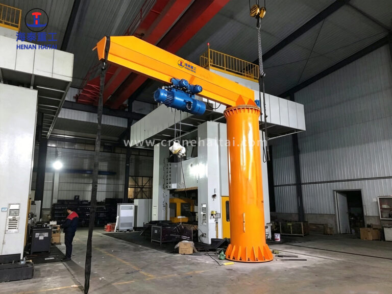
Image 2 shows a Haitai 360° floor mounted jib crane serving an assembly pit with a circular turntable. The crane’s full-rotation capability and centrally positioned column allow the spreader and hoist to follow the turntable’s full arc, placing components precisely at any angular position on the rotating workpiece. This configuration is common in engine assembly, turbine assembly, and large valve production.
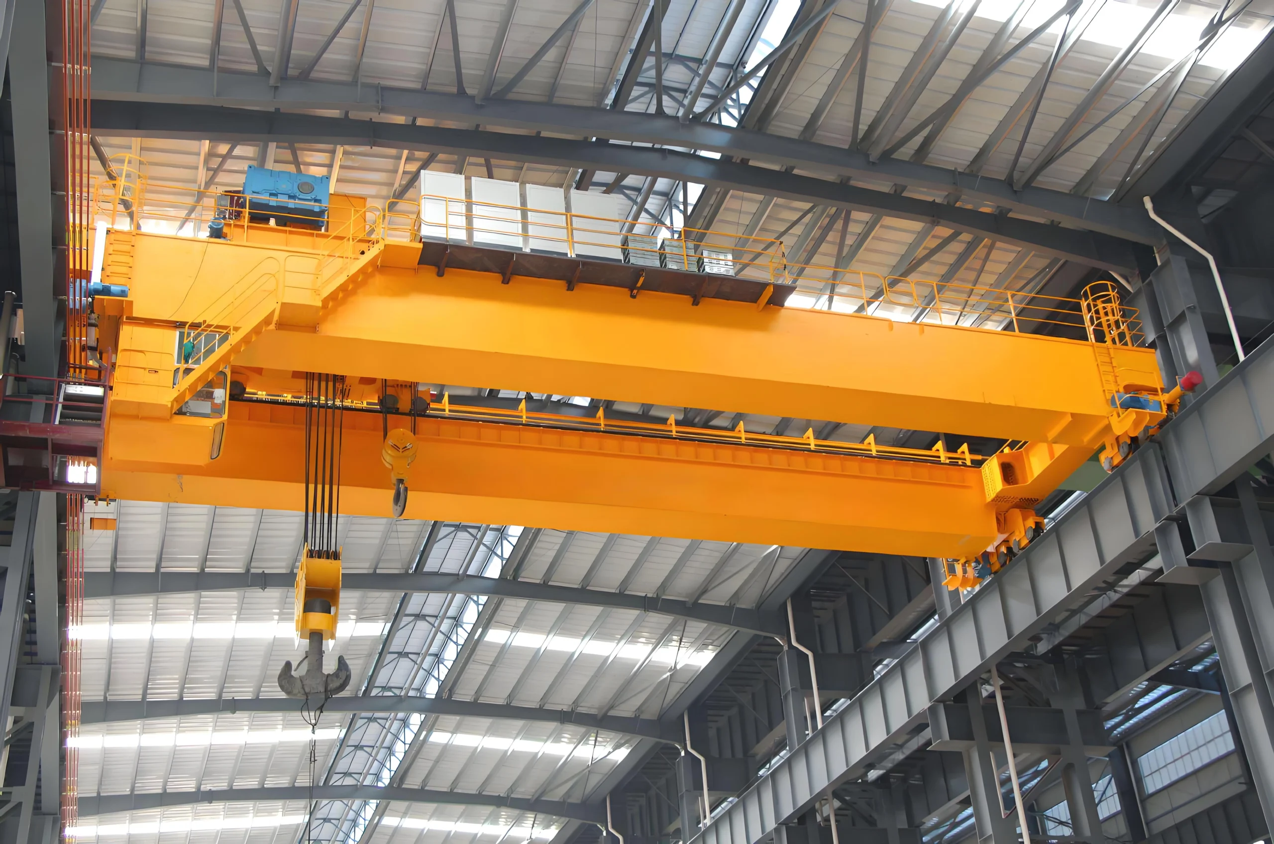
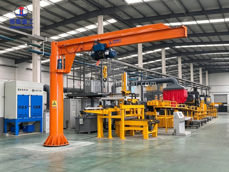
Image 3 shows a Haitai jib crane integrated alongside an automated production line in a large manufacturing facility. The jib crane handles component loading and unloading at the automated line’s feed and discharge points — tasks that require precise positioning and frequent short lifts, which floor-mounted jib cranes are optimally designed for. The crane’s compact footprint does not interfere with AGV paths or automated equipment travel zones.
In maintenance facilities — engine overhaul bays, hydraulic repair workshops, electrical equipment service centres — a floor mounted jib crane provides lifting at the specific service bench or pit position where work is performed. Unlike overhead cranes, the jib crane is available exclusively to the technician at that station, without competing with adjacent bays for crane time. This increases maintenance throughput and reduces wait time significantly in multi-bay facilities.
| Standard / Certification | Scope | Status |
| CE — Machinery Directive 2006/42/EC | Essential Health & Safety Requirements for lifting machinery | Standard on all units |
| ISO 4301-1:2016 | Crane classification A3–A4 duty | All units |
| EN 13001-1:2015 | Crane safety — General principles and requirements | Design basis standard |
| EN 13135:2013 | Cranes Safety: Design Requirements for Equipment | Electrical and mechanical equipment |
| ISO 13849-1:2023 | Safety-related parts of control system — Performance Level assessment | Control system safety circuit |
| IEC 60204-32:2023 | Safety of Machinery: Electrical Equipment of Hoisting Machines | Electrical system design |
| ISO 9001:2015 | Haitai Crane quality management system | Manufacturing quality |
| Proof Load Test Certificate | 125% of SWL proof load test before dispatch | Supplied with every unit |
| ASME B30.11 (on request) | Monorails and Underhung Cranes — US market | Available for US projects |
Every crane is proof load tested at 125% of Safe Working Load before dispatch. Load test certificate, CE Declaration of Conformity, foundation drawing, and operation & maintenance manual are supplied as standard contract deliverables.
Use the table below as a starting point. All combinations are subject to structural verification — radius and height interact with capacity to determine column section, foundation design, and slewing drive torque requirements.
| Capacity | Standard Radius Range | Standard Lift Height | Recommended Hoist | Typical Application |
| 0.5t – 1t | 3m – 6m | 3m – 6m | Electric chain hoist 0.5t–1t | Bench-level assembly, tool handling, light component transfer |
| 2t – 3t | 3m – 7m | 3m – 7m | Electric chain hoist 2t–3t | Machine tending, mould handling, packaging line service |
| 5t | 3m – 7m | 3m – 8m | Wire rope hoist 5t | Fabrication shop, engine assembly, heavy component loading |
| 8t – 10t | 3m – 6m | 3m – 8m | Wire rope hoist 8t–10t | Steel processing, press shop, heavy industrial workstation |
Source: Haitai Crane standard engineering parameters, 2026. Larger radius at higher capacity requires upgraded column section and foundation — contact engineering for project-specific confirmation.
The floor mounted jib crane’s column transfers its entire load — vertical (crane and hoist dead weight plus rated load) and horizontal (slewing torque and cantilever overturning moment) — through the base flange to the foundation. The foundation must be designed to the specific crane configuration.
Every Haitai floor mounted jib crane order includes a certified foundation design drawing as a standard deliverable. The drawing specifies: concrete grade (typically C30 minimum), foundation plan dimensions, depth, reinforcement layout, anchor bolt diameter, grade, and embedment depth, and required bolt-down torque. Do not pour foundation concrete before receiving and reviewing the Haitai foundation drawing for your specific crane configuration.
| Capacity | Typical Foundation Plan | Typical Foundation Depth | Anchor Bolt Spec (indicative) | Concrete Grade |
| 0.5t – 1t | 1,200 × 1,200 mm | 800 mm | M24 × 600 mm, Grade 8.8, 4 off | C25 minimum |
| 2t – 3t | 1,500 × 1,500 mm | 1,000 mm | M30 × 700 mm, Grade 8.8, 4–6 off | C30 minimum |
| 5t | 1,800 × 1,800 mm | 1,200 mm | M36 × 900 mm, Grade 8.8, 6 off | C30 minimum |
| 8t – 10t | 2,200 × 2,200 mm | 1,500 mm | M42 × 1,100 mm, Grade 8.8, 6 off | C35 minimum |
Foundation dimensions are indicative only and vary with soil bearing capacity, jib radius, and actual crane configuration. Haitai Crane provides project-specific foundation drawings for every order. All anchor bolt installations must be verified by a qualified civil/structural engineer at the installation site.
The slewing angle is determined by the installation environment and the physical constraints around the crane’s location. Both configurations use the same column, jib, and hoist hardware; only the slewing drive stop arrangement and control logic differ.
| Factor | 270° Slewing | 360° Full Rotation | Decision Guide |
|---|---|---|---|
| Working coverage | Three-quarter circle; one dead zone | Complete circle; no dead zone | Wall or column within radius → 270° |
| Installation context | Adjacent to wall, column, or machine | Freestanding; clearance on all sides | Open floor position → 360° |
| Cable management | Standard pendant cable; no wrap risk | Requires cable reel or drag chain system | 360° adds cable management hardware |
| Control complexity | Standard; angle stop switches | Cable reel + slip ring or drag chain | Both are production-proven solutions |
| Typical application | Machine-side service, loading dock bay | Central workstation, turntable, assembly pit | Match to physical layout |
| Cost | Slightly lower (no cable reel) | Slightly higher (cable management system) | Specify 360° only where full rotation is needed |
The floor mounted jib crane is supplied as a complete lifting package (crane + hoist + trolley) or as a crane-only unit for customers integrating their own hoist. Factory-matched hoist options:
| Hoist Type | Capacity Range | Lift Height | Duty Class | Best Application |
| Electric Chain Hoist (CD/MD series) | 0.5t – 10t | 3m – 9m | M3–M4 (FEM) | Standard production lifting, moderate cycle frequency |
| Wire Rope Electric Hoist (HC series) | 1t – 10t | 3m – 12m | M4–M5 (FEM) | Higher duty cycles, longer lift heights, robust duty |
| Variable Speed Electric Chain Hoist | 0.5t – 5t | 3m – 8m | M4 (FEM) | Precision placement, automated line integration |
| Manual Chain Hoist | 0.5t – 3t | 3m – 5m | — | Low duty, no power supply available, intrinsically safe zones |
FEM hoist duty class M3–M5 maps to crane duty class A3–A4 for the jib crane structure under typical operating patterns. Confirm actual cycle frequency with Haitai engineering to verify hoist selection.
Floor mounted jib cranes require structured preventive maintenance to achieve their rated service life and maintain CE certification. The following intervals are the minimum requirement:
| Inspection Type | Frequency | Key Items |
| Operator Pre-Use Check | Daily | Limit switches, hook latch, hoist chain/rope visual inspection, pendant controls, slewing brake |
| Lubrication Service | Monthly | Slewing ring bearing grease, slewing drive gearbox oil level, trolley wheel bearings, hoist chain lubrication |
| Mechanical Inspection | Every 3 months | Structural bolt torque check, hoist brake lining thickness, slewing drive pinion and ring gear wear inspection |
| Electrical Inspection | Every 6 months | Control panel connections, limit switch calibration, motor insulation resistance, cable condition |
| Full Structural Inspection | Annually | Weld inspection (visual + NDT on critical joints), base flange anchor bolt re-torque, overload protection test |
| Load Re-certification | Annually or per HSE | Proof load test at 100–125% SWL; re-issue of load test certificate |
Source: EN 13135:2013 – Cranes Safety: Design Requirements for Equipment; IEC 60204-32:2023. Intervals are minimum requirements — high-duty cycle applications (approaching A4 upper limit) should increase inspection frequency accordingly.
Standard configurations cover the large majority of applications. Where standard parameters do not match, Haitai Crane’s engineering team provides custom design within a 5-working-day quotation turnaround — at no charge for qualified procurement projects.
Standard lead time: 3–5 weeks for standard configurations. Custom or high-capacity designs: 5–8 weeks from drawing approval. Foundation drawing issued within 5 working days of order confirmation. Contact Haitai Crane jib crane specialist —— Mr. Simon now.














A boat jib crane is a marine-grade lifting solution designed specifically for docks, marinas, shipyards, and offshore platforms — where saltwater corrosion, confined space, and dynamic loads demand equipment built to a different standard. HaiTai Crane’s boat jib cranes deliver 0.5 to 20 tons lifting capacity, 180° to 360° rotation, and full C4–C5 marine corrosion protection from structural steel to electrical enclosures. Quick Reference: Boat Jib Crane Specifications Parameter Standard Range Custom Available Lifting Capacity 0.5 t – 20 t Up to 50 t on request Jib (Boom) Length 3 m – 10 m Up to 15 m Rotation Angle 180° / 270° / 360° Configurable Lifting Height 3 m – 12 m Customizable Hoist Type Electric chain / Wire rope Manual available Control Mode Push-button / Radio remote Cabin option Corrosion Protection Hot-dip galvanized + marine paint C4/C5 ISO 12944 Mounting Type Column / Wall / Dock-embedded Floating dock option Certification CE, ISO 9001:2015 CCS / BV on request Power Supply 380V / 50Hz (customizable) Global voltage supported What Is a Boat Jib Crane Structure and Operating Principle A…

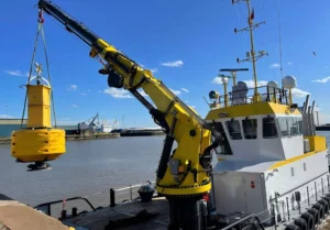
A marine arm crane is one of the most versatile pieces of deck equipment a vessel can carry. Unlike a straight-boom deck crane, a knuckle boom or articulated arm crane folds compactly when not in use, reaches over obstacles, and positions loads with precision that a fixed boom simply cannot match. For ship owners and procurement teams evaluating deck crane options, the choice between a straight boom and an articulated arm crane often comes down to one question: does your operation require the crane to work in confined spaces, reach below deck level, or handle irregular load positions? If yes, a marine arm crane is almost certainly the right choice. This page covers what marine arm cranes are, where they are used, what the key specifications mean, and how to evaluate suppliers before committing to a purchase. What Is a Marine Arm Crane? The Core Design Concept A marine arm crane — also called a knuckle boom crane or articulated marine crane — uses two or more boom sections connected by hydraulic-powered knuckle joints. This articulation allows the crane to…
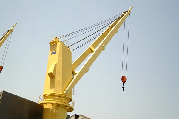
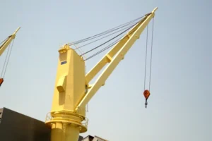
Selecting the wrong ship deck crane creates problems that follow you for the vessel’s entire operational life. Inadequate lift capacity, poor outreach, or a crane not certified by your classification society — any of these can delay port clearance, increase operating cost, or create liability exposure in the event of an incident. This page gives procurement managers, ship owners, and shipyard purchasing teams a clear, practical overview of what to look for when sourcing a ship deck crane. We cover equipment types, key technical parameters, certification requirements, and what distinguishes a reliable supplier from a risky one. HT crane manufacture and export ship deck cranes across a full capacity range — and we back every unit with classification society certification, factory load testing, and long-term spare parts support. What Is a Ship Deck Crane? The Basic Function A ship deck crane is a rotating lifting device permanently mounted on a vessel’s deck. It handles cargo loading and unloading at ports where shore-based equipment is unavailable or insufficient. It also supports deck operations, equipment transfers, and maintenance lifts during voyage. Vessel…