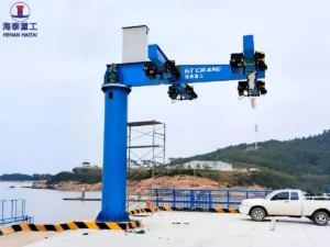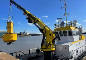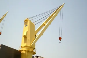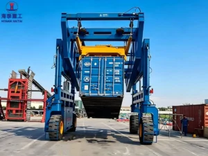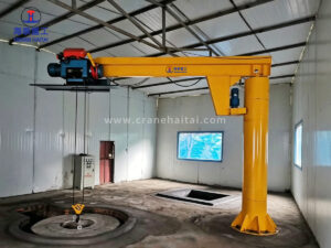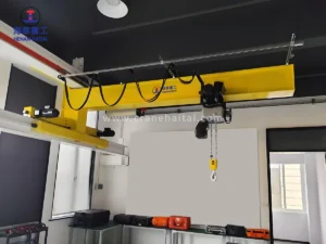


Haitai wall traveling jib crane is a wall-mounted, slewing-boom crane that mounts directly to a structural wall or building column. It consumes no floor space and imposes no foundation requirement on the workshop floor.
The jib crane’s truss-section horizontal boom carries an electric chain hoist on a motorized trolley. It ensures operators’ precise three-axis load control across a working radius of up to 12 meters and a slewing arc of up to 360°.
Working grade A5 classifies this cantilever jib crane for sustained, moderate-to-high duty operation. For example, it suits to production lines, fabrication workshops, assembly bays, and loading zones where lifting frequency is regular and consistent throughout the shift.
With a lighter structural profile than a floor mounted jib crane of equivalent radius, the wall traveling jib crane is the correct choice where floor space is at a premium, where multiple cranes must share a wall-line, or where the building structure provides a suitable and cost-effective mounting point.
The boom (cantilever arm) uses a welded steel truss design, as detailed in this following structure image. The top and bottom chords are structural steel sections (T-section or flat bar); the web members are welded between chords at a defined angle to form the triangulated lattice. This structural form is chosen specifically for long-radius cantilever applications because it achieves much lower tip deflection than a solid beam of equal weight — a critical requirement for maintaining trolley positioning and preventing the hoist from running to the boom tip under its own weight on the down-slope created by deflection.
The hoist trolley travels on the bottom chord of the truss, with the bottom chord profile machined or rolled to a standard bottom flange section (per BS 4 / DIN 1025) to accept standard electric chain hoist or wire rope hoist push or motorized trolleys.
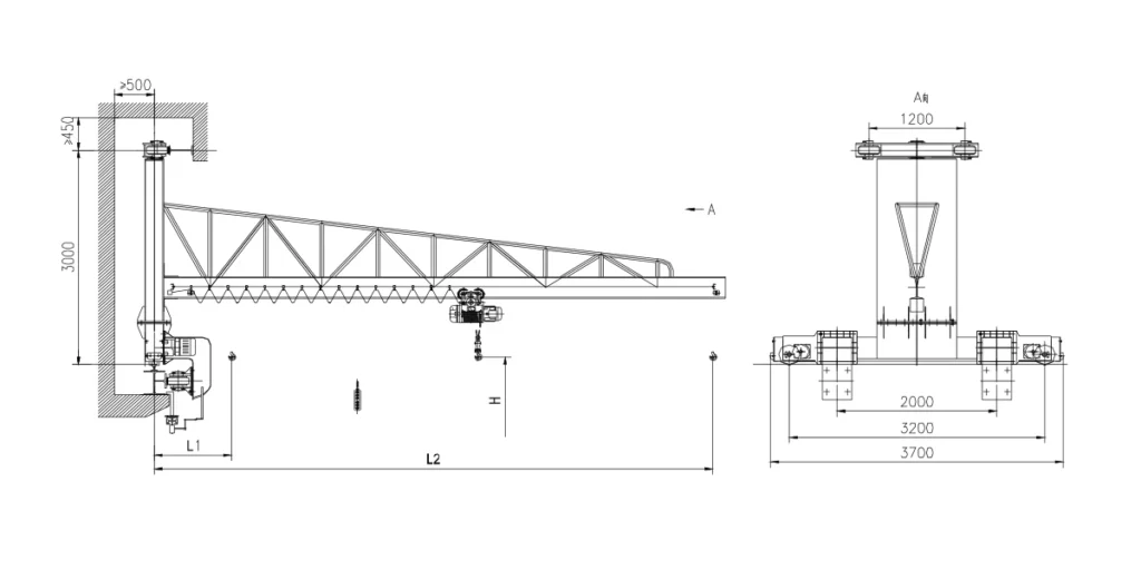
The wall bracket assembly consists of: an upper mounting plate bolted to the wall with anchor bolts (minimum embedment ≥500 mm per engineering drawing); a lower guide bracket; and the slewing pivot housing. The travel rail — width 1,200 mm (per view A of engineering drawing) — is welded to the bracket and extends along the wall to the limits of the crane’s travel zone.
The bracket is designed to transfer both the vertical load (crane dead weight + rated payload) and the horizontal overturning moment (from the cantilever boom) into the wall anchor system. The wall must be assessed by a qualified structural engineer to confirm it can carry these combined loads — Haitai provides bracket load calculation documents as a standard project deliverable.
The crane travels along the wall rail on a motorized bogie assembly. Per the engineering drawing, the bogie spans 2,000 mm (inner wheel centres), 3,200 mm, and 3,700 mm (outer dimensions). The bogie drive motor moves the complete crane assembly along the wall rail, allowing the operator to reposition the crane’s working zone along the wall. End-of-travel limit switches on the bogie prevent overrun at the ends of the rail.
The slewing assembly connects the boom to the wall bracket pivot and provides motorized rotation to the specified arc. The slewing drive uses a helical bevel gearmotor engaging a slewing ring gear, with dynamic braking for controlled stop. On 180° and 270° models, adjustable mechanical stops and limit switches define the rotation limits precisely, cutting power to the slewing motor at end positions and preventing cable wind-up on the pendant or festoon cable.
| Parameter of Wall-travelling Jib Cranes | Specification | Notes |
|---|---|---|
| Rated Lifting Capacity | 0.5t / 1t / 2t / 3t / 5t | Custom capacities on request |
| Valid Radius (L2) | 5m / 6m / 7m / 8m / 9m / 10m / 11m / 12m | From wall mounting face to hook centre |
| Near-Wall Dead Zone (L1) | Per bracket design (refer drawing) | Minimum approach distance from wall — project-specific |
| Lifting Height (H) | 2m / 3m / 4m / 5m / 6m / 7m / 8m / 10m | Hook height below boom bottom flange |
| Slewing Angle | 180° / 270° / 360° / Custom | Motor-driven slewing standard; angle defined by wall position |
| Working Grade | A5 | Suitable for regular production-line lifting duty |
| Boom Structure | Welded steel truss (chord + web construction) | From drawing: triangulated truss section — stiff, low self-weight at long radius |
| Wall Bracket | Structural steel bracket; bolted to wall | Wall embedment ≥500 mm depth; wall section ≥450 mm (per drawing) |
| Travel Rail Width | 1,200 mm (standard; per drawing view A) | Upper rail and lower guide rail spacing |
| Bogie Span | 2,000 / 3,200 / 3,700 mm (per drawing) | Bogie track widths as dimensioned in view A |
| Hoist Type | Electric chain hoist (standard) | Wire rope hoist available for 3t–5t; matched to boom beam section |
| Trolley Type | Motorized electric trolley | Manual push trolley available for 0.5t–1t light duty |
| Slewing Drive | Electric gearmotor with slewing ring | Variable speed slewing optional; pendant or radio control |
| Wall Mounting | Bolted bracket to RC wall or structural column | Wall structural capacity must be confirmed by civil engineer |
| Power Supply | 380V / 50Hz / 3-phase (standard) | Custom voltages available for export |
| Control Method | Push-button pendant (standard) | Radio remote control optional |
| Surface Finish | Primer + polyurethane topcoat | Haitai yellow (standard); red; white; RAL options — see installed examples |
| Compliance | CE Machinery Directive 2006/42/EC; ISO 9001:2015 | Load test certificate supplied as standard |
Dimension data extracted from Haitai Crane engineering drawing (Structure Image). All parameters subject to project-specific engineering confirmation.
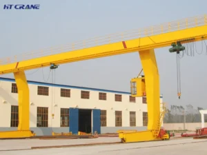
Image 1 shows two Haitai 2t wall traveling jib cranes installed in parallel on the same structural wall of a large manufacturing facility. Each jib crane is independently motorized for slewing and trolley travel, with separate pendant controls. The yellow-painted truss booms are clearly visible mounted to a shared wall bracket rail system. Conductor bar power supply runs along the wall rail. This multiple jib cranes configuration is a cost-effective alternative to a full overhead bridge crane where coverage of a defined wall-side working zone, rather than the full bay width, is required. Each crane serves its designated production stations independently, without competing for shared crane time.
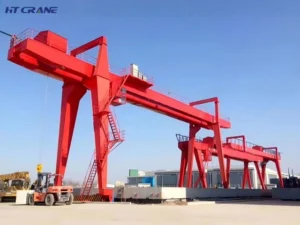
Image 2 shows a high-specification Haitai installation featuring multiple wall traveling jib cranes at multiple levels in a large-span facility. The cranes are finished in white with orange conductor bars visible along the wall rail — indicating a cleanroom-adjacent or appearance-sensitive industrial environment. The yellow low-headroom wire rope hoists are matched to the available ceiling height. This installation demonstrates the system’s scalability: a single wall line can support multiple independent crane units, each with its own hoist, serving consecutive workstations along the production wall. The conductor bar supply system eliminates cable festoon management across multiple units.
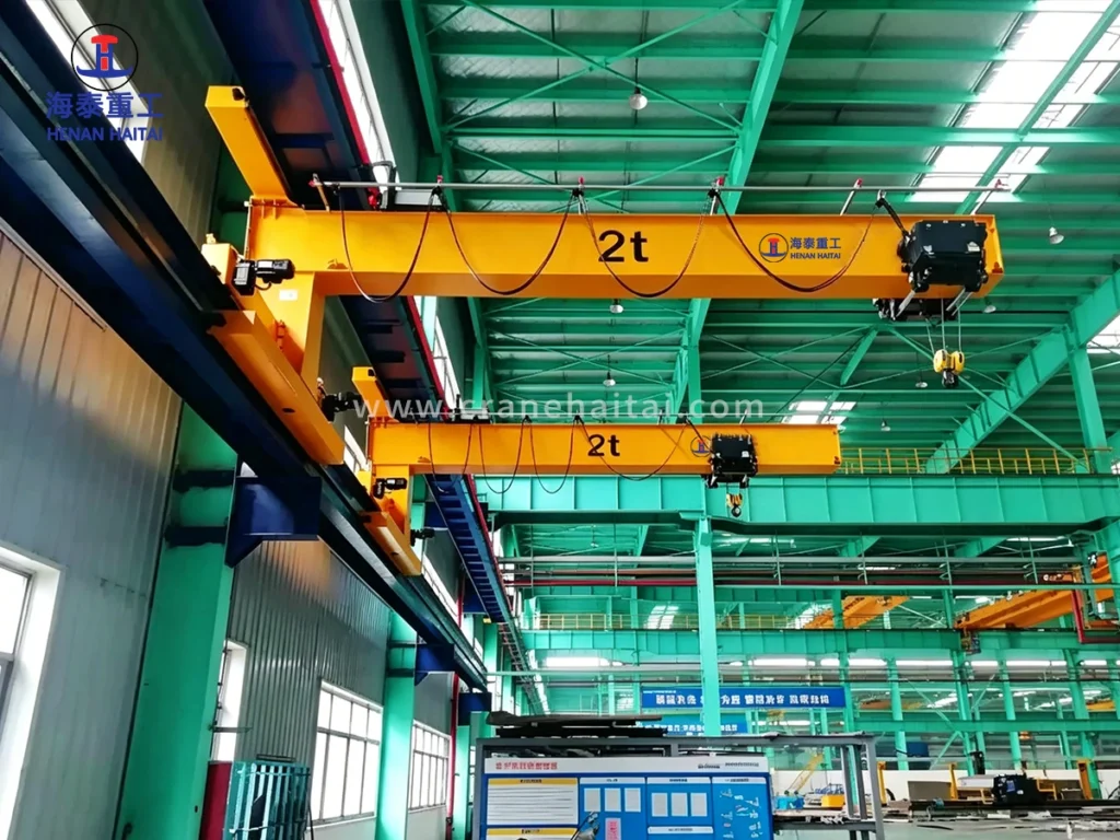
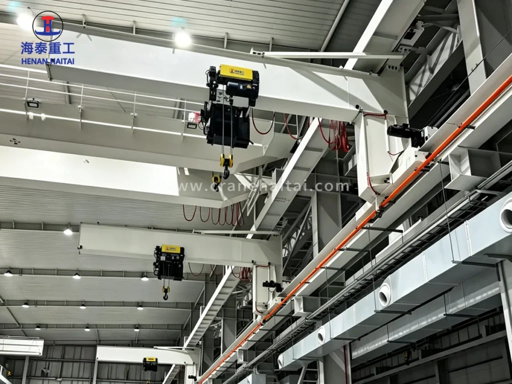
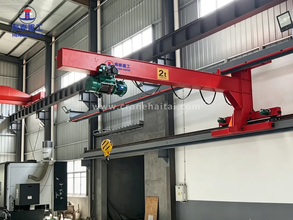
Image 3 shows a single Haitai 2t wall traveling jib crane in a red polyurethane finish, serving a machine shop bay. The truss boom structure is clearly visible in this installation — note the triangulated web members providing stiffness across the full cantilever length. The crane’s motorized travel bogies are visible on the wall-mounted rail at the right. The green wire rope electric hoist with paired motors is matched to a 2t rated capacity. The rated capacity plate on the boom (2t yellow label) is clearly displayed per CE and local safety marking requirements. This installation serves CNC machining equipment requiring regular component loading and unloading — a classic A5 duty cycle application.
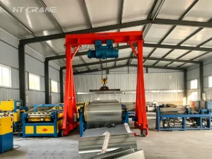
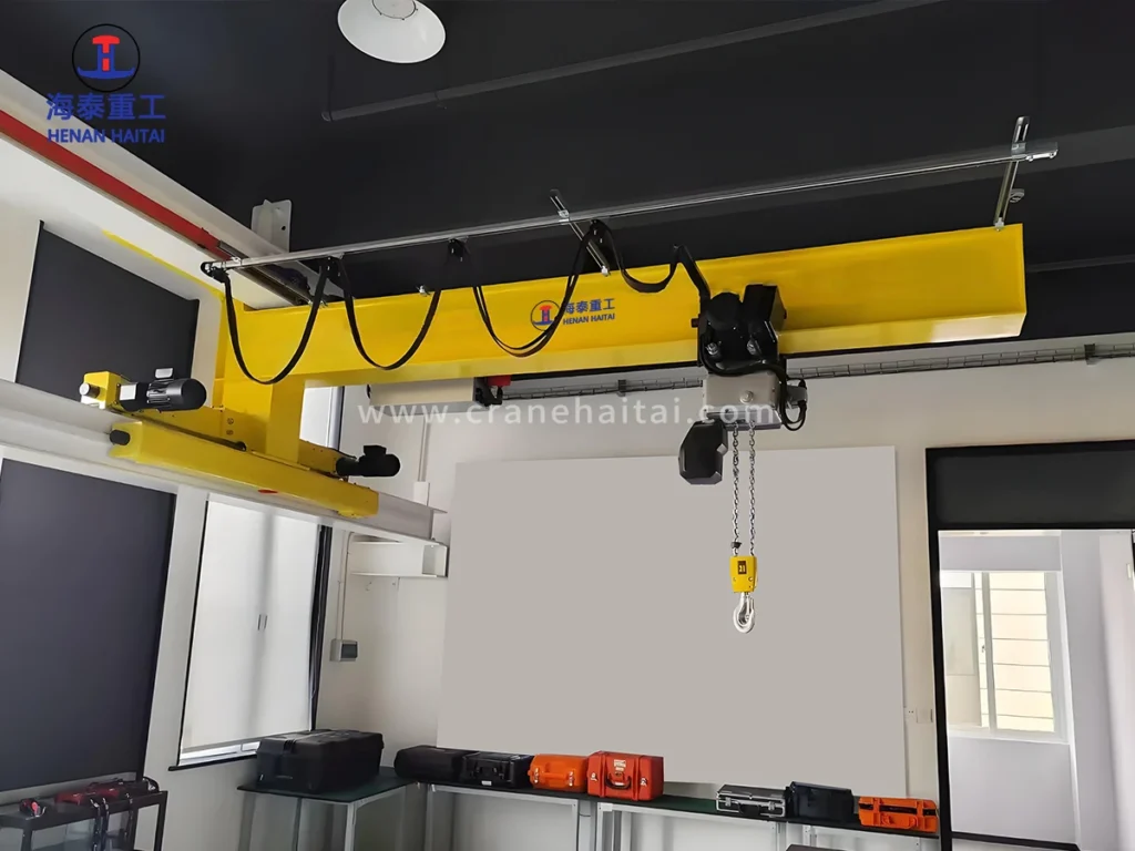
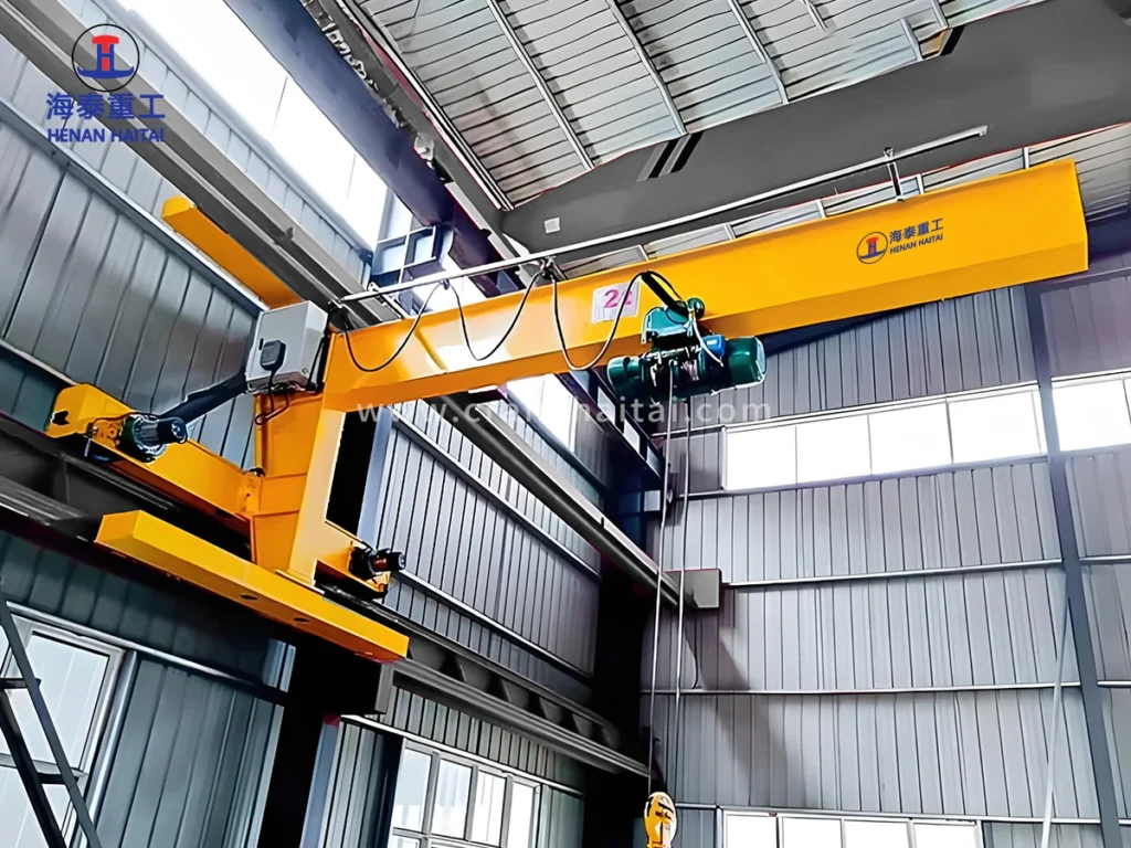
Image 4 shows a compact Haitai wall traveling jib crane in an instrument or equipment room, fitted with a light-duty electric chain hoist. This installation demonstrates the crane’s scalability to very light applications — equipment rack loading, instrument case handling, server or electrical equipment installation in enclosed technical spaces. The conductor bar (black, ceiling-mounted) manages the power supply to the hoist along the compact travel range. The boom-wall bracket assembly is compact enough to install in a standard-height room without civil modification. Tool cases and equipment cases are visible on the workbenches below — the crane serves a precision, low-frequency but ergonomically important lifting function.
Use the table below to identify the standard configuration nearest to your requirement. Boom length (working radius) and capacity interact to determine boom section, bracket design, and wall load — all are verified by Haitai’s structural engineers before manufacture.
| Capacity of Wall Traveling Jib Crane | Standard Radius Range | Lift Height Range | Recommended Hoist | Duty / Typical Application |
|---|---|---|---|---|
| 0.5t – 1t | 5m – 10m | 2m – 8m | Electric chain hoist 0.5t–1t | A5 / Light assembly line, tool handling, instrument loading |
| 2t | 5m – 12m | 2m – 10m | Electric chain hoist 2t | A5 / Component transfer, machine loading, fabrication shop |
| 3t | 5m – 10m | 2m – 10m | Electric chain hoist / Wire rope hoist 3t | A5 / Heavy assembly, mould transfer, production line service |
| 5t | 5m – 8m | 2m – 10m | Wire rope hoist 5t | A5 / Press shop, steel processing, heavy workstation duty |
Source: Haitai Crane standard engineering parameters, 2026. Longer radius at higher capacity increases wall bracket load — structural engineering confirmation required.
Critical: The wall or structural column on which the crane is mounted must be assessed and confirmed as structurally adequate by a qualified civil or structural engineer before installation. Haitai Crane provides bracket load calculation documents (vertical reaction, horizontal moment, anchor bolt forces) as a standard deliverable. Do not install without engineering sign-off on the mounting structure.
| Parameter | Minimum Requirement | Notes |
|---|---|---|
| Wall type | Reinforced concrete structural wall or structural steel column | Brick / block / partition walls are NOT suitable without independent frame |
| Wall section depth | ≥450 mm (RC wall) | As dimensioned in Haitai engineering drawing |
| Anchor embedment | ≥500 mm into RC wall | Chemical or mechanical anchor system; brand and grade to Haitai specification |
| Concrete grade | C25 minimum for anchor zone | Higher grade preferred; specify actual concrete grade to Haitai engineering |
| Steel column option | Structural section with flange adapter plate | Haitai provides adapter plate design; site welding or bolting by certified installer |
| Wall load capacity | Confirmed by structural engineer per Haitai bracket load doc | Combined vertical + moment load; Haitai supplies load calculation document |
| Rail fixing | Wall-plug anchor or through-bolt at specified centres | Fixing pattern per Haitai installation drawing — supplied with every order |
Haitai Crane provides bracket reaction force calculations (vertical load, overturning moment, horizontal shear) for every project. These documents must be reviewed by the site structural engineer before installation proceeds.
The correct slewing angle is determined by the crane’s physical installation position and the coverage zone required. All configurations use the same boom and hoist hardware; the difference is in the slewing drive stop arrangement and cable management.
| Slewing Angle | Typical Installation | Coverage Zone | Cable Management | Notes |
|---|---|---|---|---|
| 180° | Flat wall, no obstruction on wall face | Full semicircle in front of wall | Standard pendant festoon or conductor bar | Most common; standard for wall-mounted cranes |
| 270° | Wall corner; one side partially clear | Three-quarter circle; one 90° zone blocked | Conductor bar or cable reel | Corner bays; wall with one adjacent obstruction |
| 360° | Structural column; clearance on all sides | Full circle; complete working arc | Cable reel or slip ring required | Best for column-mounted, pillar-centre installations |
| Custom | Non-standard bay geometry | Specified arc; mechanical stops at limits | Engineered to application | Available on request; quotation required |
Note: 360° slewing requires cable reel or electrical slip ring to manage pendant and hoist power cables through continuous rotation. Haitai Crane engineers both solutions — specify preferred approach when ordering.
The wall traveling jib crane is supplied as a complete package (crane + hoist + trolley) or crane-only. All hoists are factory-matched to the boom beam section and working grade A5 requirement.
| Hoist Type | Capacity | Lift Height | Duty Class | Best Fit Application |
|---|---|---|---|---|
| Electric Chain Hoist (CD/MD series) | 0.5t – 5t | 2m – 9m | M4–M5 (FEM) | Production line, regular moderate-cycle lifting |
| Low-Headroom Electric Chain Hoist | 0.5t – 3t | 2m – 6m | M4 (FEM) | Height-constrained bays; maximises hook height |
| Wire Rope Electric Hoist (HC series) | 1t – 5t | 2m – 12m | M5 (FEM) | Higher duty, longer lift height, robust cycle demands |
| Variable Speed Electric Chain Hoist | 0.5t – 3t | 2m – 8m | M4–M5 (FEM) | Precision placement, automated line, delicate component handling |
FEM hoist duty class M4–M5 aligns with crane working grade A5 under standard operating cycle assumptions. Confirm actual lift frequency with Haitai engineering to verify hoist selection for your specific application.
| Standard / Certification | Scope | Status |
|---|---|---|
| CE — Machinery Directive 2006/42/EC | Essential H&S Requirements for lifting machinery | Standard on all units |
| ISO 4301-1:2016 | Crane classification A5 duty | All units |
| EN 13001-1:2015 | Crane safety — General principles and requirements | Design basis standard |
| EN 13135:2013 | Cranes Safety: Design Requirements for Equipment | Electrical and mechanical components |
| EN ISO 13849-1:2023 | Safety-related parts of control system — Performance Level | Control system safety circuit |
| IEC 60204-32:2023 | Safety of Machinery: Electrical Equipment of Hoisting Machines | Electrical system design |
| ISO 9001:2015 | Haitai Crane quality management system | Manufacturing quality |
| Proof Load Test Certificate | 125% SWL proof load test before dispatch | Supplied with every unit |
| ASME B30.11 (on request) | Monorails and Underhung Cranes — US market standard | Available for US export projects |
Every jib crane is proof load tested at 125% of Safe Working Load before dispatch. Load test certificate, CE Declaration of Conformity, wall bracket load calculation document, installation drawing, and operation & maintenance manual are supplied as standard contract deliverables.
Standard configurations address the large majority of applications. Haitai Crane’s engineering team provides custom design quotations within 5 working days — at no charge for qualified procurement projects.
To receive a technical proposal and quotation, provide the following:
Standard lead time: 3–5 weeks for standard configurations. Multi-unit orders or custom designs: 5–8 weeks from drawing approval. Wall bracket load calculation document and installation drawing issued within 5 working days of order confirmation.
Click here to place your order.














What Is A Floor Mounted Jib Crane? Haitai floor mounted jib crane is a free-standing pillar jib crane anchored directly to the workshop floor via a reinforced concrete foundation. Fitted with an electric chain hoist or wire rope hoist on a motorized trolley, it provides 360° or 270° slewing coverage across a working radius of up to 8m. Its special structure and flexible rotation makes it the standard lifting solution for dedicated workstations, assembly cells, production lines, and maintenance bays where a full overhead crane is either unavailable or impractical. Unlike wall-mounted or column-mounted jib cranes, the floor-mounted pillar design imposes no load on building structure. We install it independently of the building frame, so we can position it anywhere on the factory floor and relocate it when the production layout changes. We can position floor-mounted jib cranes at a production machine, a loading dock, a welding bay, and a material transfer point. Structural Design & Engineering Details Column and Base Flange The main column is a structural steel circular hollow section (CHS) manufactured from Q345B plate, rolled and seam-welded…