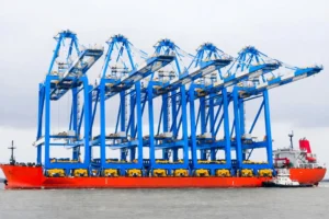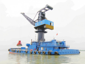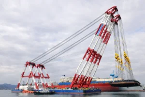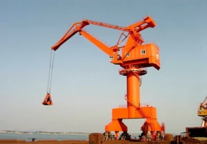


A shipyard without the right gantry crane is not a shipyard — it is a steel fabrication yard with ambition. The gantry crane defines what a yard can build, how large a vessel it can handle, and how fast production moves from block assembly to launch. An undersized or poorly specified crane becomes the bottleneck that limits every other investment in the facility.
Shipyard gantry cranes are among the most technically demanding lifting machines in any industrial sector. They span widths of 80–170 metres, lift loads of 100–3000 tonnes, and operate in a marine environment that subjects every structural and electrical component to continuous salt-air corrosion. Getting the specification right from the outset determines whether the crane serves the yard reliably for 30 years or becomes a source of unplanned downtime that disrupts the production schedule.
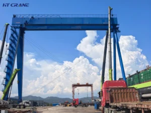
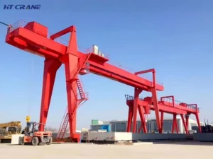
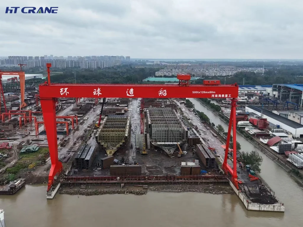
A shipyard gantry crane — also called a goliath crane, portal gantry crane, or shipbuilding gantry crane — is a large double-leg gantry structure that spans the full width of a shipbuilding berth, drydock, or block assembly area. It travels on ground-level rails along the length of the working area, covering the entire production zone with its main hoist and trolley.
The crane handles the largest and heaviest lifts in the shipyard: ship hull block sections weighing hundreds of tonnes, engine modules, deck sections, and major structural assemblies. It is the piece of equipment that makes large vessel construction physically possible.
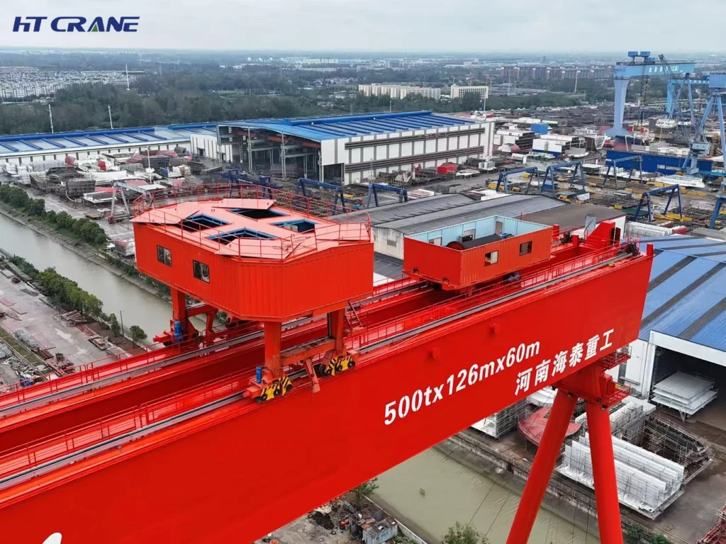
Shipyard gantry cranes carry two separate hoist systems on a single bridge:
Main hoist — the primary lifting system, carrying the crane’s rated maximum SWL. Typically a heavy-duty wire rope crab trolley travelling on rails on top of the main girders. Used for all heavy block lifts.
Auxiliary hoist — a secondary hoist with lower capacity but often higher speed. Used for rigging, positioning, and handling smaller items that do not require the main hoist. The auxiliary hoist allows the crane to perform two different lifting tasks simultaneously or in rapid sequence without the main hoist being involved in light accessory work.
The main hoist trolley travels across the full span including the cantilever sections, providing coverage of the entire working area beneath the crane.
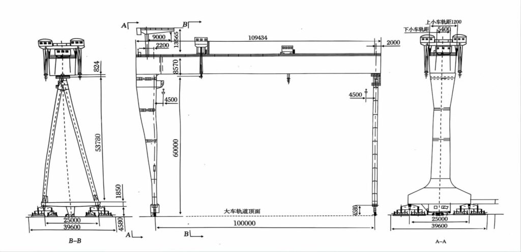
The main girder of a shipyard gantry crane is a large box section — fabricated from structural plate into a closed rectangular section with internal stiffening. The box section provides the bending stiffness required for the long spans involved while keeping the structure as light as possible relative to its load-bearing capacity.
Two leg types are commonly used, and the choice affects how the crane handles differential rail settlement or misalignment:
Rigid leg — a fixed-connection leg that transfers all lateral forces from the girder to the rail foundation. Used on one side of the crane.
Flexible (hinged) leg — a leg with a pin connection at the top or bottom that allows limited rotation. Used on the other side of the crane to accommodate differential thermal expansion and minor rail misalignment without inducing stress into the main girder. This rigid + flexible leg combination is standard on large shipyard gantry cranes worldwide.
| Parameter | Specification Range |
|---|---|
| Lifting Capacity (Main Hoist) | 100T – 3000T |
| Lifting Capacity (Auxiliary Hoist) | 20T – 500T |
| Span (Between Rail Centrelines) | 80m – 170m |
| Cantilever Length (Each Side) | 10m – 20m |
| Total Working Width | Span + 2 × cantilever |
| Lifting Height | 30m – 100m (above rail level) |
| Hoisting Speed — Main | 0.5 – 5 m/min (full rated load) |
| Hoisting Speed — Auxiliary | 2 – 15 m/min |
| Trolley Travel Speed | 10 – 40 m/min |
| Gantry Travel Speed | 10 – 30 m/min |
| Drive System | AC VFD — all motions |
| Rail Type | Heavy crane rail (P43 – P120 or equivalent) |
| Power Supply | Conductor rail or trailing cable |
| Work Duty Class | A6 – A7 (ISO 4301 / FEM 1.001) |
| Girder Type | Box girder, welded plate construction |
| Leg Type | One rigid + one flexible (standard) |
| Design Standard | GB/T 14406, EN 13001, FEM 1.001 |
| Classification | CCS, ABS, BV, DNV GL, LR (buyer’s specification) |
| Certification | CE (EU Machinery Directive 2006/42/EC), ISO 9001 |
Speed and performance on a large shipyard crane varies with load. Understanding the speed-load relationship is important for production planning:
| Load Level | Main Hoist Speed | Notes |
|---|---|---|
| 100% SWL (full rated load) | 0.5 – 2 m/min | Controlled, slow lift for maximum load |
| 50% SWL | 1 – 4 m/min | Standard working range for most block lifts |
| 25% SWL or less | 2 – 8 m/min | Light rigging and positioning work |
| Unladen (hook only) | Up to 15 m/min | Rapid return for next lift |
Variable frequency drives on all motions provide smooth speed control across the full range — eliminating the step-changes that older contactor-controlled systems imposed and reducing mechanical shock on the rope, drum, and structural connections.
| Parameter | Shipyard Standard Specification |
|---|---|
| Structural Steel Grade | Q345B or equivalent (minimum) |
| Weld Standard | GB/T 11345, EN ISO 5817 — Level B |
| NDT Requirement | UT + MT on all primary structural welds |
| Primary Coating System | Sa 2.5 blast + zinc-rich primer + epoxy mid + PU topcoat |
| Minimum DFT | 300 microns total |
| Additional Treatment | Stripe coat on all weld seams and exposed edges |
| Fasteners | Hot-dip galvanized or stainless steel for external connections |
| Electrical Enclosures | IP55 minimum; IP65 for exposed outdoor installations |
| Operating Temperature | -20°C to +50°C (cold weather packages available) |
The primary application of a shipyard gantry crane is lifting hull block sections — prefabricated ship hull units weighing 100 to 600 tonnes — from the assembly hall floor or outdoor fabrication area and positioning them on the building berth for welding into the growing hull structure.
Modern shipbuilding uses block construction methodology: the hull is fabricated in sections in a controlled indoor or semi-outdoor environment, then lifted by gantry crane and assembled in sequence on the building berth. The gantry crane makes this production method possible. Without a crane of sufficient capacity and span, blocks must be reduced in size — which increases the number of joints to weld on the berth, slows production, and reduces weld quality control.
A 500T main hoist capacity with 120m span covers the standard building berth of a medium to large shipyard producing vessels in the 10,000–50,000 DWT range. Larger yards building VLCCs, LNG carriers, or large containerships require 800T–3000T capacity and spans up to 170 metres.
Shipyard gantry cranes over drydocks support both new construction and ship repair and conversion operations. In repair mode, the crane handles engine removal and replacement, propeller and rudder handling, deck equipment removal, and large structural section replacement.
Drydock cranes also operate in a more confined geometry than building berth cranes. The hook must reach to the drydock floor level — which may be 15–25 metres below quay level — while maintaining clearance above the ship’s superstructure at the upper position. Hook height specification for drydock applications requires careful coordination with the drydock geometry and the vessel profiles to be handled.
Shipyards using inclined slipways for vessel launch require gantry cranes that can operate at the slipway gradient and position loads accurately onto the cradle system. Slipway cranes must be designed for the lateral force component that arises from operating on an inclined rail foundation — a load case that does not apply to flat building berth cranes and must be explicitly accounted for in the structural design.
For slipway applications, rail gradient tolerance and the level compensation system for the crane cab and hoist machinery are important specifications. Equipment that relies on gravity-referenced systems — oil lubrication, fluid levels, and some braking systems — must be designed or adapted for the slipway gradient.
Large gantry cranes are also deployed in offshore fabrication yards — assembling oil platform topsides, jacket structures, and living quarter modules. These structures weigh 500 to 2,000 tonnes and require a crane of equivalent or greater capacity to lift and position them during assembly.
The specification profile for an offshore module yard is similar to a shipyard but with some important differences: loads are typically more irregular in shape and weight distribution; the lift plan for each module must be individually engineered; and the yard may need to handle loads that approach or exceed the crane’s standard SWL through engineered tandem lifts using two cranes simultaneously.
All hoist, trolley, and gantry travel drives use AC VFD technology as standard. This provides smooth, stepless speed control from zero to maximum — critical for the precise positioning required when lowering a 300-tonne block section onto a building berth where alignment tolerances are measured in millimetres. Hard stops and speed steps — characteristic of older contactor-controlled drives — are eliminated, reducing mechanical shock and extending the service life of ropes, drums, and structural connections.
Load swing on a large shipyard crane — with a hoist height of 50 metres and a heavy block section suspended from a long rigging spread — creates significant positional error at the landing point and imposes dynamic loads on the crane structure. Our standard anti-sway system uses drive motion profiling — the trolley and gantry accelerate and decelerate on a calculated profile that minimizes pendulum swing. For high-precision applications, active anti-sway with laser-based position feedback reduces residual swing at the hook to less than 200mm at full travel speed.
Shipyard environments are among the most corrosive industrial settings. Salt-laden air, humidity, and tidal splash zones accelerate coating degradation on exposed structural and mechanical components. Our standard coating system for shipyard gantry cranes specifies:
Total minimum DFT of 300 microns. On structures within 50 metres of the waterline or in tidal zones, an additional sacrificial anode system is available for substructure protection.
All shipyard gantry cranes are supplied with a comprehensive safety system as standard:
Shipyard gantry cranes are designed and manufactured to the requirements of major classification societies. Classification is required for cranes operating at classified shipyard facilities and for cranes that will lift marine equipment requiring classification certification. We manufacture to:
The classification surveyor attends factory acceptance testing and issues the crane certificate directly. We coordinate the surveyor schedule as part of our standard project delivery process.














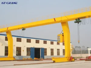
When the load is heavy, the span is wide, or the hook height requirement exceeds what a single girder crane can deliver — a double girder gantry crane is the answer. It is the structural choice for heavy industry, and for good reason: two main girders share the load, allow a higher-positioned hoist, and provide the structural rigidity needed for large spans and demanding duty cycles. Buyers often reach the double girder decision after outgrowing a lighter crane or after realizing that a single girder model cannot meet their hook height or span requirements. The challenge then becomes specification: double girder cranes involve more variables, more civil infrastructure, and larger capital commitment than their lighter counterparts. This page walks you through what defines a double girder gantry crane, what to specify, where it fits, and how to evaluate a supplier for a purchase of this significance. What Is a Double Girder Gantry Crane? A double girder gantry crane uses two parallel horizontal girders — the main beams — supported at each end by leg structures that run on ground-level rails.…

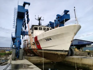
If you manage a marina, boatyard, or naval facility, you already know the pain: vessels stuck in the water waiting for maintenance, slipways that damage hulls, and cranes that simply weren’t built for boats. A marine travel lift solves all three problems in a single machine. It lifts, moves, and launches vessels safely — without fixed rails, without hull damage, and without slowing down your yard. This page covers everything you need to evaluate a marine travel lift: what it does, where it works, what makes ours different, and the full technical specs. If you are ready to specify a unit, our engineering team responds to enquiries within 24 hours. Product Description A marine travel lift — also called a boat travel lift, mobile boat hoist, or self-propelled boat hoist — is a rubber-tyred gantry crane designed specifically for vessel handling. The portal frame straddles the boat in the water. Polyester slings are positioned under the hull. The vessel is then lifted clear and driven anywhere on land. No rail tracks. No fixed infrastructure. Just one machine that handles haul-out,…

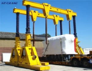
Looking for a heavy lifting system that handles loads other cranes simply cannot? Our hydraulic gantry crane delivers lifting capacity from 10 to 1,000 tons, millimeter-level synchronization precision, and a modular structure that assembles quickly on any job site — indoors or out. Trusted across power generation, shipbuilding, metallurgy, and civil engineering, this is the heavy lifting equipment built for projects where performance cannot be compromised. What Is a Hydraulic Gantry Crane? A hydraulic gantry crane is a heavy-duty lifting system powered entirely by a hydraulic drive system. It consists of six core components: a gantry frame, lifting mechanism, traveling mechanism, hydraulic power unit, electrical control system, and safety protection devices. The system raises, positions, and moves extremely heavy loads with stepless speed control and ±1mm synchronization accuracy across multiple lifting points. It operates on standard AC 380V / 50Hz power supply or a self-contained diesel power unit — making it deployable anywhere, with or without grid power. Core Technical Specifications Parameter Specification Lifting Capacity 10 – 1,000 tons Span 8 – 35 m Lifting Height 4.5 – 12 m…