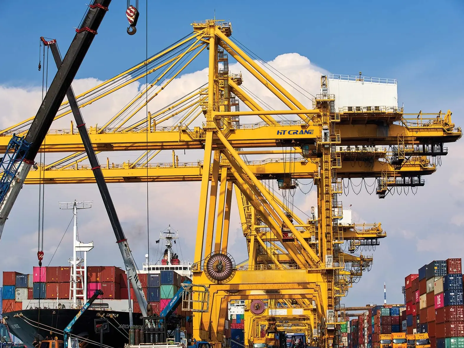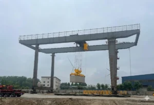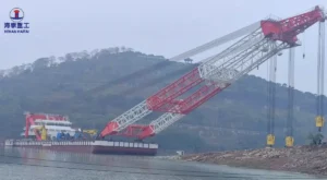
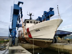
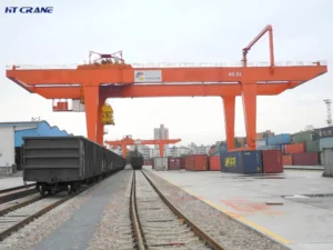
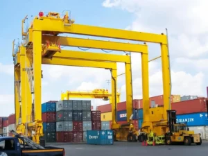
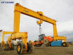
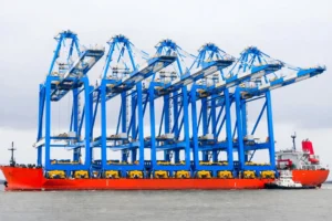
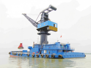
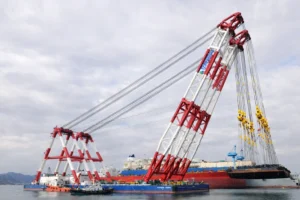
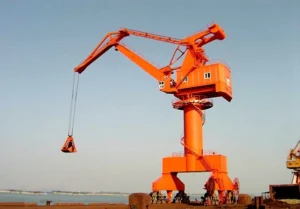
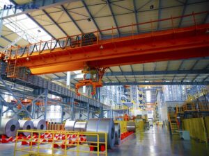
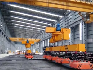
Ship-to-shore cranes are large rail-mounted gantry crane positioned at the quayside of a container terminal. They are certified, configurable, and built for continuous heavy-duty operation, and they are the most critical equipment for modern container terminals. They directly determine vessel turnaround times, berth productivity and port competitiveness. Vessel turnaround time is the most costly variable in container terminal operations. The faster containers move between ship and shore, the lower the cost per port call—and Ship-to-Shore cranes are the key equipment for controlling this efficiency. Get the specification wrong, and no amount of RTG efficiency or gate optimization will compensate.
This STS crane complete guide covers all the information required for terminal operators, port planners, and procurement teams to make informed decisions. Whether you are planning a new fleet of quay cranes or evaluating upgrade options, this is your indispensable and authoritative reference.
The following guide covers: what is Ship-to-shore crane, how STS cranes work, how STS cranes are classified, what their technical parameters mean (outreach, lifting capacity), which scenario can STS cranes applied, how to choose the right configuration, and how to do STS crane maintenance for your berth and vessel profile.
What Is an Ship-to-Shore Crane? Overview and Core Function
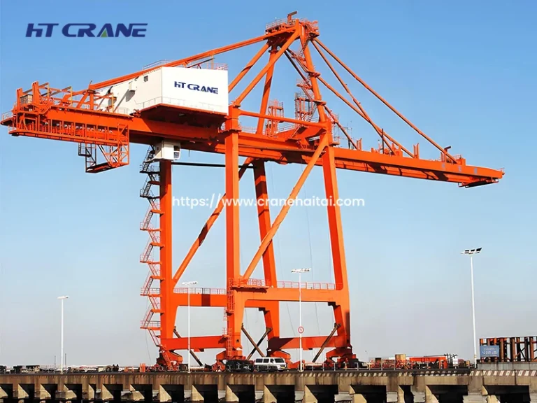
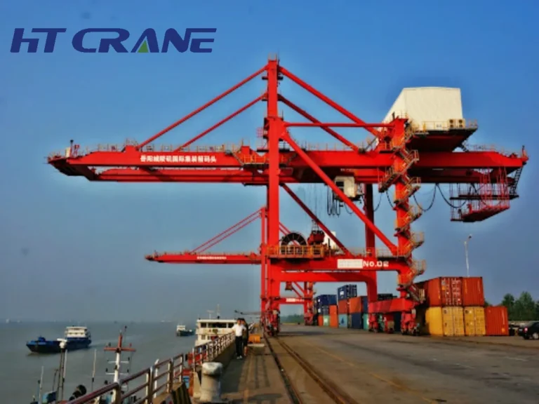
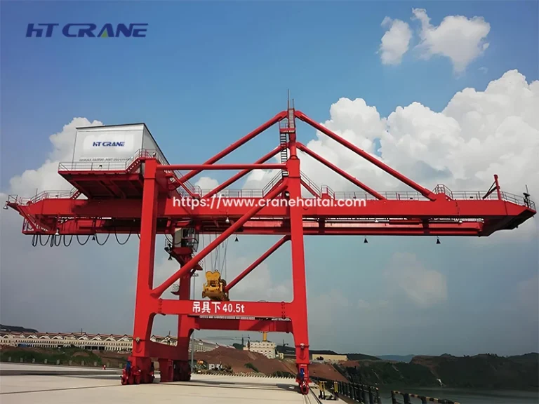
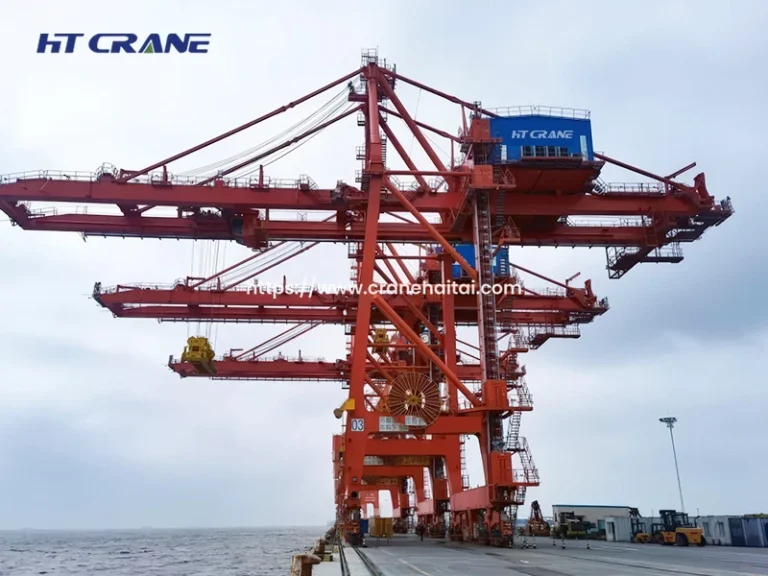
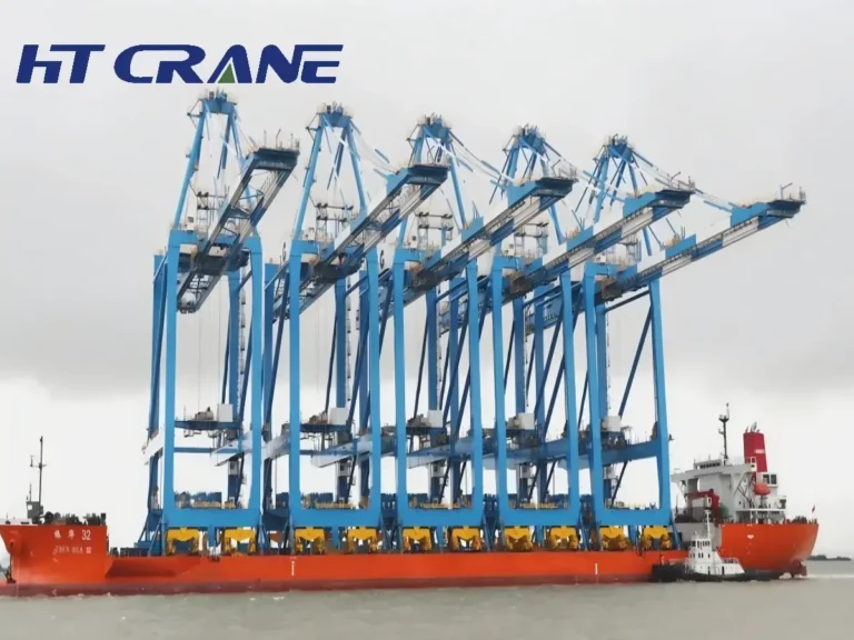
A Ship-to-Shore crane (STS crane or Quay crane) is a large rail-mounted gantry crane installed on the quayside of a container terminal. Its function is straightforward: lift containers from container ships berthed alongside the quay and transfer them to quayside transport equipment (AGVs, terminal tractors, or straddle carriers), or reverse the process during vessel loading.
STS cranes are among the largest mobile structures in routine industrial use. A modern Post-Panamax STS crane stands 80–120 meters above the quay rail, has a waterside outreach of 60–70 meters to reach containers across the full beam of the world’s largest container vessels, and weighs 1,500–2,500 tonnes or more depending on configuration.
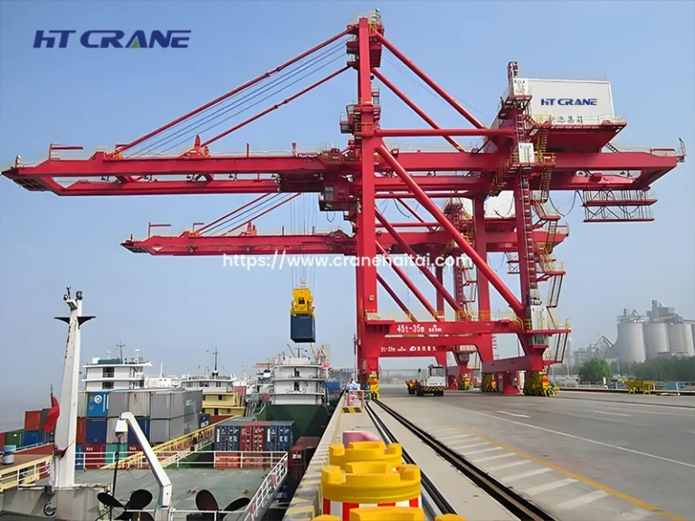
How Does an Ship-to-Shore Crane Work?
The operating cycle of an STS crane follows a defined sequence:
- Trolley positions over target container bay on the vessel
- Spreader lowers to lock onto container ISO corner castings
- Hoist lifts container clear of the ship’s hatch coaming or adjacent boxes
- Trolley travels inboard along the boom and girder to the landside
- Container lands on waiting transport equipment or direct to ground
- Spreader returns to vessel for next pick
A fully optimized STS crane cycle — including trolley travel, hoist motion, and landing — runs 90–120 seconds under skilled operation. At that rate, a single crane achieves 25–35 gross moves per hour (GMPH). High-performance automated cranes at advanced terminals have demonstrated 40+ GMPH under optimal conditions.

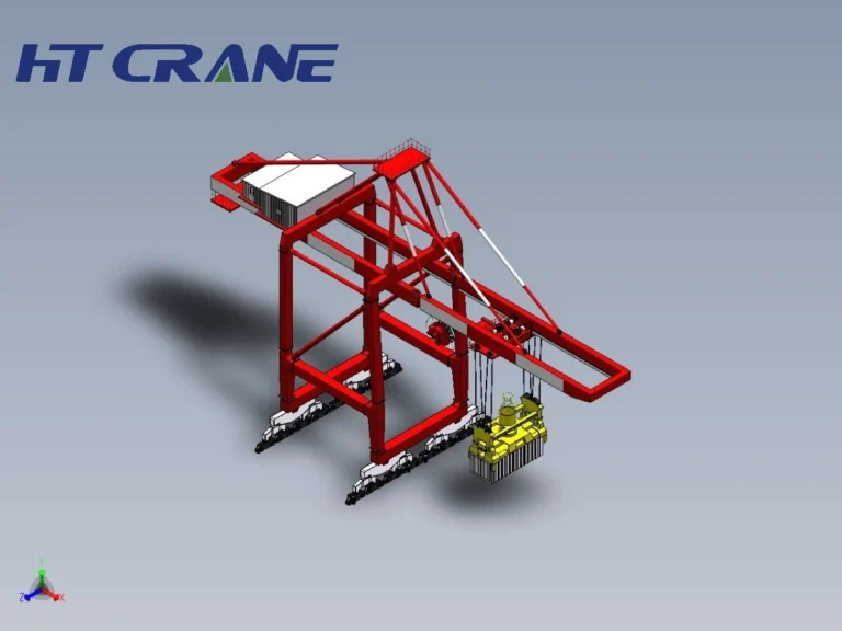
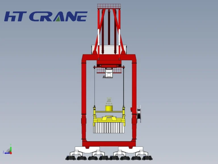
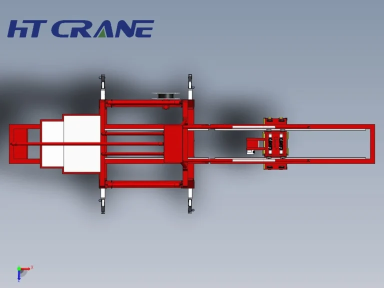
Types of Ship-to-Shore Cranes: Classification and Design Variants
STS crane types are classified by structural configuration, vessel size capability, and hoist arrangement. Understanding the classification is essential before issuing any specification or procurement enquiry.
Classification by Vessel Size (Outreach Requirement)
| STS Crane Class | Outreach | Vessel Width Coverage | Typical Vessel Class |
| Panamax | 35–40m | Up to ~13 container rows | Panamax vessels (≤32.3m beam) |
| Post-Panamax | 45–55m | Up to ~18–20 rows | Post-Panamax (32–49m beam) |
| Super Post-Panamax | 55–65m | Up to ~22–24 rows | Neo-Panamax, ULCV (up to 61.5m beam) |
| Ultra Large (ULCV) | 65–75m | Up to ~26 rows | 24,000 TEU+ vessels (>60m beam) |
Source: PIANC Working Group 158 port infrastructure guidelines; ZPMC, Liebherr Marine Cranes, Konecranes published specs, 2022–2024. Vessel beam data: IHS Markit Container Vessel Fleet Database, 2024.
Single and Twin Lift Ship-to-Shore Cranes
Most STS cranes operate with a single spreader capable of handling one 20-foot or 40-foot container per cycle. Twin lift (or dual hoist) STS cranes use a tandem spreader to pick two 20-foot containers simultaneously, doubling effective throughput per crane movement. Tandem lift STS cranes are standard specification at high-throughput terminals and are a significant driver of GMPH performance.
Low-Profile vs High-Profile STS Crane Design
Some terminals require STS cranes to pass under fixed structures such as bridges. Low-profile STS crane designs — where the boom folds to minimize air draft when not in operation — address this constraint. Standard (high-profile) configurations dominate in open port environments without overhead clearance restrictions.
Ship-to-Shore Crane Structure: Main Components Explained
Understanding STS crane components is essential for evaluating supplier proposals, assessing maintenance requirements, and specifying performance guarantees.
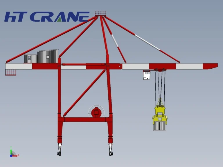
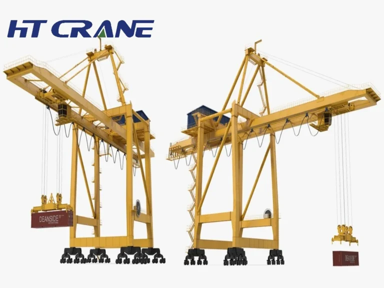
Main Structural Components of STS Crane
Portal Frame and Legs: The ground-level steel structure that carries the entire crane load to the quay rail. STS cranes run on two sets of rails — waterside and landside — with the portal opening designed to allow quayside transport equipment to pass beneath the crane while it operates.
Boom (Waterside Outreach Arm): The hinged structural arm that extends over the vessel. The boom length determines waterside outreach and therefore the maximum vessel beam the crane can serve. During vessel transit or storm conditions, the boom is raised to near-vertical via hydraulic luffing cylinders. Boom length directly defines the STS crane class.
Back Reach (Landside Girder): The section extending landward from the portal frame. Back reach (typically 15–25 meters) determines how far inboard containers can be placed — a key input to quayside transport and buffer zone design.
Trolley: The carriage that travels along the boom and back reach, carrying the hoist and spreader. Trolley travel speed is a primary determinant of crane cycle time; modern high-speed STS cranes achieve 180–240 m/min.
Hoist Mechanism: The wire rope reeving system, drum, and motor assembly controlling vertical movement. Hoist speed on modern STS cranes runs 60–120 m/min under rated load, with higher speeds on empty hook return. Dual hoist STS cranes carry two independent hoist assemblies on the trolley.
Spreader: The telescopic below-hook device locking onto ISO container corner castings. Spreaders telescope between 20-foot and 40-foot settings; twin-20 spreaders handle two 20-foot containers simultaneously. Spreader weight (typically 15–25 tonnes) is included in the crane’s rated lifting capacity.
Counterweight: Located at the rear of the back reach girder, it balances the boom and suspended load. Counterweight mass is precisely calculated to the structural design — modifications require re-engineering.
Machinery House: The enclosed equipment deck at the top of the portal frame, housing main hoist motors, trolley drives, control panels, VFD systems, and transformer equipment. Maintenance access is via elevator or fixed ladders.
Operator Cabin: Mounted on the trolley for full downward visibility. Modern cabins include anti-vibration isolation, climate control, ergonomic seating, and in automated configurations serve as a monitoring station rather than primary control position.
Rail and Travel Bogies: STS cranes travel along the quay on two pairs of rails. Travel bogie wheel count, diameter, and load rating determine quay load per running meter — a critical structural parameter that must be verified against quay capacity.
Ship-to-Shore Crane Specifications: Key Technical Parameters
These parameters must be determined before any enquiry to STS crane manufacturers or suppliers — they drive both structural design and operational performance.
| Parameter | Panamax STS | Post-Panamax STS | Super PP / ULCV STS | Reference |
| Lifting Capacity (SWL) | 40–50t | 50–65t | 65–80t+ | Under spreader, ISO 4301-1 |
| Waterside Outreach | 35–42m | 45–55m | 60–75m | Boom tip to rail centerline |
| Back Reach | 12–18m | 15–22m | 18–25m | Landside working range |
| Lift Height (above rail) | 30–35m | 35–45m | 42–52m | Hatch coaming to max lift |
| Lift Height (below rail) | 10–15m | 12–18m | 15–20m | Below-deck hatch access |
| Trolley Speed | 120–180 m/min | 150–210 m/min | 180–240 m/min | Loaded condition |
| Hoist Speed (loaded) | 60–90 m/min | 75–105 m/min | 90–120 m/min | At rated SWL |
| Gantry Travel Speed | 30–45 m/min | 35–50 m/min | 40–55 m/min | Along quay |
| Total Crane Weight | 800–1,200t | 1,200–1,800t | 1,500–2,500t+ | Structural + mechanical |
| Rail Gauge | 15.24m (50ft) | 15.24–18m | 18–30.48m | Center-to-center |
Outreach Calculation: Matching STS Crane to Vessel Fleet
The most critical STS crane specification decision is waterside outreach. It must cover the full beam of the widest vessel in your terminal’s design call — with at least one container row of margin.
Required outreach = (vessel beam ÷ 2) + (quay face to waterside rail distance) + safety margin (2–3m). Example: 60m beam ULCV → (30m) + (8m quay setback) + (2.5m margin) = 40.5m from waterside rail ≈ 65–70m boom tip outreach.
Underspecifying outreach means cranes cannot serve the full vessel width — a permanent structural constraint that cannot be corrected after commissioning.
Ship-to-Shore Crane Application: Where and How STS Cranes Are Used
Container Terminal Quayside Operations: The primary STS crane application is vessel loading and discharge at dedicated container terminals. A modern deep-sea terminal typically deploys 2–5 STS cranes per berth operating simultaneously on a single vessel. Gang productivity of 100–150 GMPH across a 3–5 crane gang is standard at major hub terminals; leading terminals in Ningbo, Singapore, and Rotterdam regularly exceed this benchmark.
Multi-Purpose and Break-Bulk Terminals: Some STS crane configurations are adapted for terminals handling both containers and break-bulk or project cargo. These cranes typically include secondary hoist systems with hook configurations in addition to the spreader assembly, and may be specified with higher lifting capacity (80–120t) for heavy out-of-gauge cargo.
Transshipment Hubs: Transshipment terminals — where containers transfer between mother vessels and feeder ships rather than moving to/from hinterland — have particularly demanding STS crane productivity requirements. Port Klang, Colombo, and Tanjung Pelepas are examples of major transshipment hubs where STS crane GMPH performance directly determines terminal competitiveness.
Ship-to-Shore Crane Automation: From Manual to Fully Automated
Automation is the defining trend in STS crane technology. The spectrum ranges from manually operated cranes to fully automated systems with machine vision and AI-assisted landing.
Four Degree of STS Crane Automation
| Level | Description | Productivity Impact | Example Deployments |
| Manual | Full operator control from trolley cabin | Baseline | Majority of global terminals |
| Semi-Automated | Automated hoist landing; operator manages trolley and travel | +10–20% vs manual | Many European terminals |
| Remote Operation | Operator controls from shore-based remote cabin | Comparable to manual; safer | APM Terminals Rotterdam |
| Fully Automated | Machine vision, RFID, PLC; minimal operator involvement | +15–25% vs manual at scale | Yangshan Phase 4, TACT Felixstowe |
Source: Terminal automation benchmarking, Port Technology International, 2023; Yangshan Phase 4 operational reports, SIPG, 2022–2023.
Electrification and Regenerative Braking
Modern STS cranes are almost universally electrically driven via quayside power supply. Regenerative braking systems — which recover energy during hoist lowering and return it to the grid — have reduced STS crane energy consumption by 20–30% compared to earlier resistive braking designs. New terminal projects in the EU and major Asian ports specify regenerative drive systems as standard.
STS Crane vs RTG Crane: Understanding the Operational Difference
STS and RTG cranes serve entirely different functions in the container handling chain — understanding the distinction is essential for integrated terminal planning.
| Factor | STS Crane | RTG Crane |
| Function | Vessel-to-quay container transfer | Container yard stacking and retrieval |
| Location | Fixed to quay rail | Mobile in container yard |
| Scale | 80–120m tall, 1,500–2,500t | 15–20m tall, 200–500t |
| Rail / Mobility | Rail-fixed along quay | Rubber-tired, relocatable |
| Throughput Driver | Gross moves per hour (GMPH) | Container stacks per hour |
| Automation Maturity | Advancing rapidly | Well-established semi/full automation |
How to Choose a Ship-to-Shore Crane: STS Crane Selection Guide
Step 1 — Define Your Design Vessel
Every STS crane specification starts with the design vessel: the largest vessel your terminal is designed to handle. Vessel beam determines required outreach; vessel LOA and TEU capacity inform berth length and crane spacing; hatch coaming height informs required lift height. Specify to your terminal’s 20-year vessel size outlook — not current maximum call. Container vessels have grown consistently for five decades, and STS cranes specified today will still be in service when vessels are larger.
Step 2 — Determine Required Productivity
Target GMPH per crane drives hoist speed, trolley speed, and automation level selection. For 30 GMPH: standard speed specification is adequate. For 35+ GMPH: high-speed hoist and trolley drives are required. For 40+ GMPH: semi-automated or automated systems are necessary to achieve consistency. Productivity specifications should be guaranteed contractually, with defined measurement conditions.
Step 3 — Evaluate Tandem Lift Requirement
Tandem lift STS cranes (dual hoist, twin-20 spreader) deliver meaningfully higher throughput for terminals with high proportions of 20-foot containers. If your vessel profile includes significant 20-foot box traffic, specify tandem lift capability from the outset — retrofitting a standard trolley to tandem lift is not practical after manufacture.
Step 4 — Confirm Quay Structural Capacity
STS cranes are among the heaviest pieces of port equipment per running meter. Quay load capacity — expressed as tonnes per running meter of rail — must be confirmed before STS crane weight is finalized. For new quay construction, the STS crane specification should inform the structural design. For existing quays, a structural assessment is required before procurement.
Step 5 — Qualify Ship-to-Shore Crane Manufacturers and Suppliers
| Qualification Criterion | What to Verify |
| Reference installations | Comparable outreach, capacity, and terminal throughput — request operational availability data |
| Design documentation | FEM/CMAA structural calculations, weld qualification records, load test certificates |
| Delivery record | On-time delivery and commissioning at comparable-scale projects |
| Spare parts commitment | 15–20 year parts availability in writing; regional warehouse preferred |
| Local service capability | Regional service engineers on contract — not factory-only dispatch |
| Compliance certification | CE marking (EU), ISO 9001:2015, relevant national port authority certification |
Major STS crane manufacturers: ZPMC (China) holds approximately 70–80% of global STS crane market share. Others include Liebherr (Germany/Ireland), Konecranes (Finland), and Mitsui E&S (Japan).
Ship-to-Shore Crane Maintenance: Ensuring Long-Term Availability
High-throughput container terminals target 95%+ mechanical availability for STS crane fleets. Achieving this requires structured preventive maintenance — not reactive repair.
| Inspection Type | Frequency | Key Focus Areas |
| Pre-Shift Operational Check | Daily | Limit switches, spreader twist locks, brake function, cabin systems |
| Routine Lubrication Service | Weekly | Trolley rail, wire rope, sheave bearings, travel bogie |
| Intermediate Mechanical Inspection | Monthly | Wire rope condition, sheave and drum wear, hoist brake lining |
| Structural & Electrical Inspection | Annually | NDT weld inspection, load test certification, electrical system audit |
| Major Overhaul | Every 5–10 years | Wire rope replacement, major mechanical component overhaul |
| Boom Luffing System | Per OEM schedule | Hydraulic cylinder seals, structural pin inspection |
Source: EN 13135:2013 – Cranes Safety: Design Requirements for Equipment; FEM 1.001 maintenance framework; OEM maintenance documentation from ZPMC and Konecranes, 2022–2024.
STS Crane Safety Requirements
STS crane safety requirements in major jurisdictions include: annual third-party structural inspection and load test certification; electronic overload protection (load moment indicator, 110% rated capacity cutoff); anti-collision systems (trolley-to-end, crane-to-crane, and personnel detection); redundant braking on all motion axes; emergency stop systems accessible from cabin, machinery house, and ground level; wind speed monitoring with automatic travel lock above threshold (typically 20 m/s operating limit, 72 m/s survival wind design criterion). In EU ports, compliance with Machinery Directive 2006/42/EC is mandatory.
Summary of Ship-to-Shore Crane Guide
The Ship-to-Shore crane is not just a piece of port terminal equipment — it is the primary productivity asset in container terminal operations. Specifying it correctly, from outreach and lift height to automation level and quay load, determines your terminal’s commercial capability for 25–30 years.
Key decisions in sequence: define your design vessel and 20-year vessel size outlook; derive outreach from vessel beam with appropriate margin; specify tandem lift if your container mix warrants it; confirm quay structural capacity before finalizing crane weight; target productivity and automation level to your throughput requirements; and qualify STS crane manufacturers on reference installations and long-term service commitment — not unit price alone.
Every major container terminal investment starts and ends with the STS crane specification. Get this right, and the rest of the terminal can be optimized around it.
Frequently Asked Questions
Q1: What is the lifting capacity of a typical Ship-to-shore crane?
STS crane lifting capacity (Safe Working Load, SWL) is specified under the spreader — meaning it includes the weight of the spreader bar itself (typically 15–25 tonnes on large cranes) in addition to the container payload. Panamax STS cranes are typically rated at 40–50 tonnes SWL; Post-Panamax at 50–65 tonnes; Super Post-Panamax and ULCV cranes at 65–80+ tonnes. The maximum container gross mass under ISO 668 is 36 tonnes for a 40-foot container, so most STS cranes have structural capacity well above typical container weights. Twin-lift configurations must carry the combined weight of two containers plus the tandem spreader.
Q2: How tall is a modern automated STS crane?
STS crane height varies by class. A Panamax crane stands approximately 55–70 meters above quay rail level; Post-Panamax cranes are typically 75–90 meters; Super Post-Panamax and ULCV-class cranes range from 90–120 meters or more to the top of the structure. The boom, when raised to its transit position, adds additional height. Boom-down (working) height determines air draft clearance for passing vessels at neighboring berths and is a critical input to port approach channel design and bridge clearance planning.
Q3: What is the difference between a Ship-to-Shore crane and a dock crane?
The term dock crane is a generic descriptor for any crane operating at a port or dock — it can include ship-mounted cranes, floating cranes, or general-purpose harbor cranes. A Ship-to-Shore crane specifically refers to the rail-mounted quayside gantry crane designed for container transfer between vessel and quay: a precise, high-cycle machine optimized for ISO container handling. The distinction matters in procurement contexts because specifying an STS crane implies a defined set of structural standards (FEM, ISO, PIANC guidelines) and performance requirements that do not apply to general dock crane specifications.
Q4: How long does an STS crane last?
A well-maintained STS crane operating at its specified duty classification should achieve a 25–30 year structural service life. Key factors: accurate duty classification at the time of specification (underspecified cranes accumulate fatigue ahead of design life), quality of structural weld execution, adherence to preventive maintenance and wire rope replacement schedules, and avoidance of systematic overloading. Mid-life refurbishment is common and cost-effective — electrical and drive system modernization, cabin upgrade, and spreader fleet replacement typically occur at 12–15 years and extend operational life without replacing the primary structure.
Q5: What automated STS crane systems are used at leading terminals?
The most advanced automated STS crane deployments integrate machine vision (camera-based container position detection), RFID-based container tracking, anti-sway control algorithms, and AI-assisted landing systems. Yangshan Phase 4 (Shanghai International Port Group) is the most cited example of a fully automated deep-sea container terminal, with automated STS cranes, AGVs, and automated stacking cranes operating with minimal human intervention. APM Terminals Maasvlakte II (Rotterdam) operates semi-automated STS cranes with remote cabin operation from a shore-based control room. Full automation is technically feasible but operationally complex; most terminals are deploying semi-automated systems as the practical near-term standard.
Related Standards & References
- ISO 4301-1:2016 – Cranes: Classification, General
- FEM 1.001 – Rules for the Design of Hoisting Appliances (6th Edition)
- EN 13135:2013 – Cranes Safety: Design Requirements for Equipment
- PIANC Working Group 158 – Port Infrastructure for Container Terminals
- ISO 668:2020 – Series 1 Freight Containers: Classification, Dimensions and Ratings
- Machinery Directive 2006/42/EC (EU)
- CMAA Specification 70 – Top Running Multiple Girder Bridge Cranes
Suggested Related Blogs: