
Efficient vessel handling is no longer a secondary consideration for marina operators, shipyard managers, and naval facility planners. As fleets grow larger and maintenance schedules become more demanding, the marine travel lift has become a core operational asset — not simply a convenience.
The challenge most buyers face is not finding a travel lift for sale. It is finding the right one. Tonnage, span, steering configuration, and manufacturer capability all interact. A mismatch in any one of these areas affects operational efficiency, vessel safety, and long-term maintenance costs from the first season of operation.
This guide gives procurement teams and facility planners a clear, structured framework for evaluating marine boat lifting equipment. It covers how these systems work, how to define your capacity and span requirements, which applications suit which configurations.
What Is a Marine Travel Lift
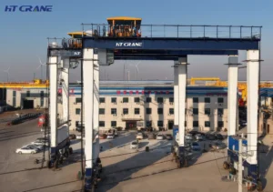
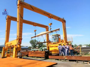
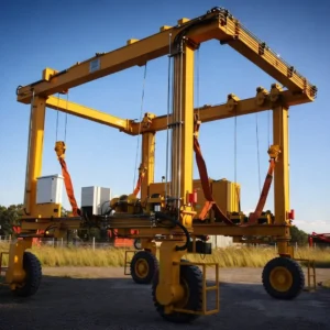
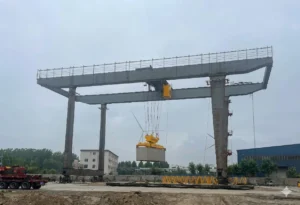
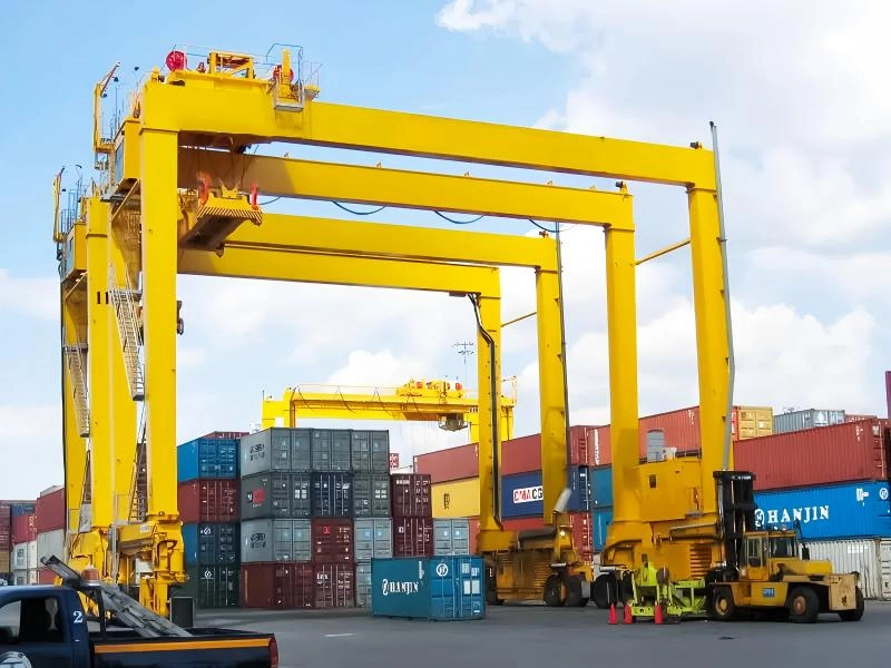
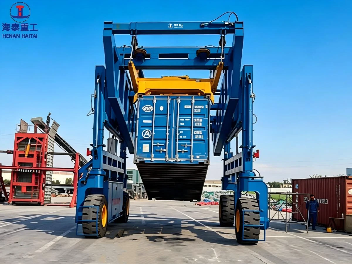
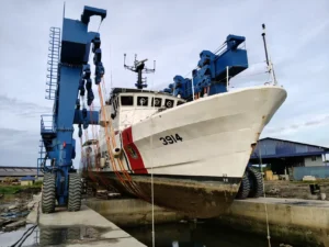
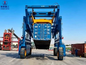
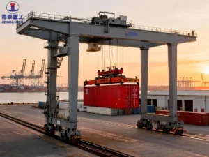
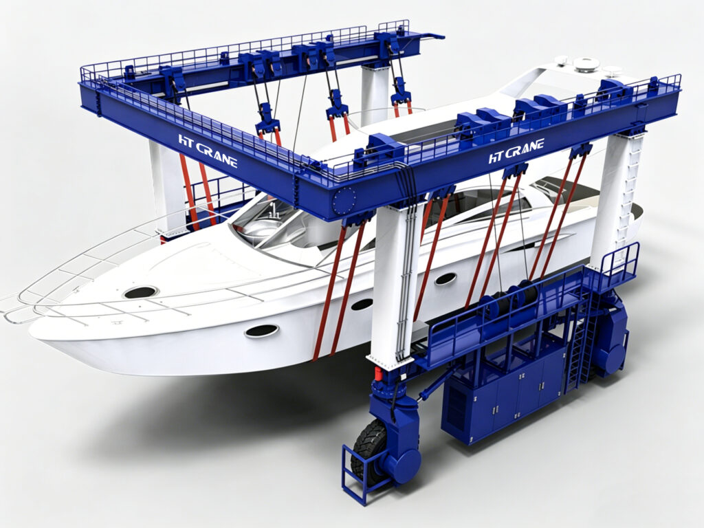
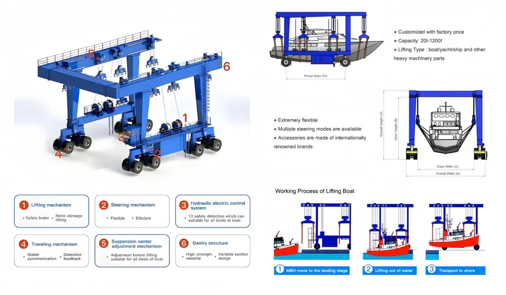
also called a mobile boat hoist or boat hoist crane — is a self-propelled rubber-tired gantry crane designed to lift vessels from the water, transport them across a hardstand, and position them for maintenance, storage, or dry docking. One integrated machine handles the complete haul-out cycle without transferring the vessel between systems.
Core Structural Components
- Lifting frame and crossbeam. The primary structural element. The clear distance between the legs — the span — determines the maximum vessel beam the system can accommodate. This is one of the two most critical dimensions in any marine travel lift specification.
- Hydraulic lifting system. Synchronized hydraulic cylinders raise and lower the sling beam with controlled, even load distribution across the vessel’s hull contact points. Synchronization accuracy directly affects hull stress during the lift.
- Sling mechanism. Nylon or polyester textile slings cradle the hull beneath the waterline. Sling width, quantity, and positioning vary by vessel type. The sling configuration must match your vessel mix — monohulls, multihulls, and flat-bottomed craft each require different arrangements.
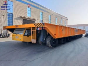
- Wheel assemblies and drive system. Solid rubber tires on diesel-hydraulic or electric drive units. Multi-axle configurations distribute load across a larger hardstand area and improve maneuverability in tight marina lanes.
- Steering system. Standard two-wheel, four-wheel, or all-wheel crab steering. Crab steering — which moves the entire machine laterally without frame rotation — is essential for facilities with narrow lanes or dense vessel storage layouts.
Common Capacity Ranges
| Configuration | Capacity Range | Typical Application |
|---|---|---|
| Small marina system | 10–50 tons | Small boats, fishing vessels, RIBs |
| Medium shipyard system | 50–150 tons | Yachts, medium commercial vessels |
| Heavy-duty travel lift | 150–500+ tons | Large yachts, naval vessels, workboats |
How Marine Travel Lifts Work
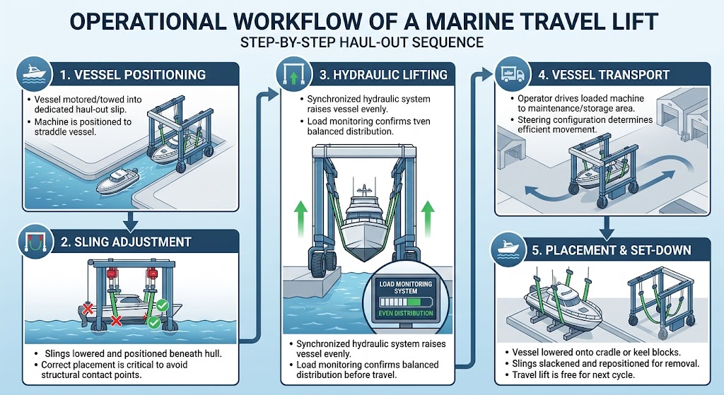
The operational workflow of a marine travel lift follows a consistent sequence. Understanding each stage helps facility managers plan hardstand layouts, lane widths, and operator procedures before equipment arrives.
- Vessel positioning. The vessel is motored or towed into the haul-out slip — a dedicated water berth aligned with the travel lift’s travel path. The operator positions the machine to straddle the vessel symmetrically.
- Sling adjustment. Slings are lowered into the water and positioned beneath the hull at manufacturer-specified contact points. Correct sling placement is critical — incorrect positioning transfers load to structurally vulnerable hull areas.
- Hydraulic lifting. The synchronized hydraulic system raises the sling beam evenly, lifting the vessel clear of the water. Load monitoring systems confirm even distribution across sling points before travel begins.
- Vessel transport. The operator drives the loaded machine across the hardstand to the designated maintenance or storage position. Steering configuration determines how efficiently this movement occurs in the available space.
- Placement and set-down. The vessel is lowered onto keel blocks or cradle supports. Slings are slackened and repositioned for removal. The travel lift is then free for the next haul-out cycle.
Understanding Marine Travel Lift Tonnage and Span
Lifting capacity — expressed in metric tons — is the specification most buyers focus on first. Arriving at the right number requires more than identifying your heaviest vessel.
How to Define Your Tonnage Requirement
Start with the maximum displacement of the heaviest vessel in your current fleet. Then apply a working buffer of 20–30% above that figure. This buffer protects against operating consistently at maximum rated capacity, which accelerates wear on structural members, hydraulic components, and wheel assemblies.
Do not specify to your current maximum if fleet composition is likely to change. A marina expanding from recreational sailing vessels to larger motor yachts within five years should specify for the anticipated fleet — not the present one.
Tonnage Selection Factors
- Vessel displacement. Full load displacement — including fuel, water, crew, and equipment — is the correct figure to use, not light ship weight. The difference can be significant for commercial and work vessels.
- Safety margin. A 20–30% capacity buffer above maximum expected load is standard engineering practice for lifting equipment in continuous commercial operation.
- Future fleet expansion. Define your five to ten year fleet development plan before finalizing capacity. Upgrading to a higher-capacity travel lift after installation is a major capital project — not a routine equipment swap.
- Asymmetric load considerations. Vessels with unusual weight distribution — large engines aft, heavy deck equipment forward — may impose uneven sling loads. Confirm with your supplier that the hydraulic synchronization system handles realistic load asymmetry within specification.
Span — the clear inside width between the travel lift legs — is the dimension that buyers most commonly underestimate. For many facilities, span is a more critical constraint than lifting capacity.
A vessel’s beam width must fit within the travel lift’s leg clearance with a safe margin on each side. A 50-ton catamaran with a 9-meter beam requires a travel lift spanning more than 9 meters in clear leg-to-leg distance — regardless of weight. Standard configurations range from approximately 5 meters to 30 meters. Custom spans beyond 30 meters are available from specialist manufacturers but add lead time and engineering cost.
Key Dimensional Parameters
Span — the clear inside width between the travel lift legs — is the dimension that buyers most commonly underestimate. For many facilities, span is a more critical constraint than lifting capacity.
A vessel’s beam width must fit within the travel lift’s leg clearance with a safe margin on each side. A 50-ton catamaran with a 9-meter beam requires a travel lift spanning more than 9 meters in clear leg-to-leg distance — regardless of weight. Standard configurations range from approximately 5 meters to 30 meters. Custom spans beyond 30 meters are available fromspecialist manufacturers but add lead time and engineering cost.
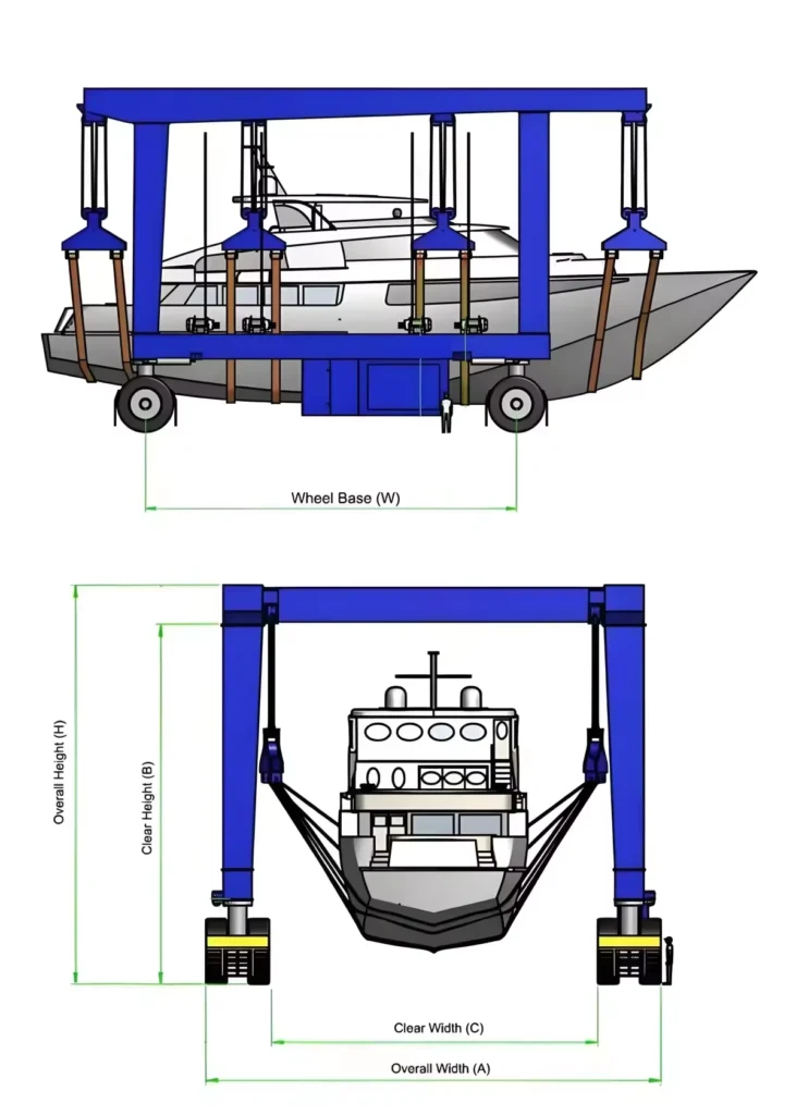
Inside clear width (span). Rail centerline to rail centerline distance available for vessel passage. Always measure your widest vessel — including fixed appendages such as outboard brackets and davits — and add a minimum 300–500mm clearance margin on each side.
Lifting height. The vertical distance from the waterline or ground level to the underside of the crossbeam at maximum elevation. Vessels with tall superstructures, masts, or high freeboard require greater lifting height. Confirm against your tallest vessels — not your average fleet height.
Wheelbase. The distance between front and rear axle sets. Longer wheelbase improves stability under load but requires wider turning space. Confirm your hardstand turning radius against the manufacturer’s turning data before finalizing the configuration.
Common Applications of Marine Travel Lifts
Marina Boat Handling
Marinas are the highest-volume application for marine travel lifts in the 15–150 ton range. Key use cases include seasonal haul-out and launch for yacht and powerboat fleets, antifouling and hull maintenance cycles, and winter dry storage management. For marina operators, cycle time and ease of operation are the primary performance metrics — a facility launching 15 boats on a busy spring weekend needs a reliable, fast haul-out system, not the most technically complex one available.
Commercial Shipyards
Shipyard applications demand higher duty cycles and greater vessel diversity than marina operations. Workboat maintenance, fishing vessel repair, and ferry operations all place different hull geometry and weight distribution demands on the travel lift and sling system. Mid-range systems in the 100–300 ton category with all-wheel steering and adjustable sling configurations handle the broadest range of commercial vessel types efficiently.
Naval and Government Facilities
Patrol vessel maintenance, rescue craft handling, and military vessel support operations require heavy-duty marine travel lifts with enhanced safety redundancy, corrosion protection, and — for sensitive installations — access-controlled operation. Duty cycle requirements for naval facilities typically fall in the ISO 4301 M7 to M8 classification range, significantly above civilian marina standards.
Offshore and Industrial Marine Operations
Support vessel maintenance at offshore logistics bases and industrial dockyards involves large, heavy vessels operating in harsh environments. Travel lifts for these applications require confirmed structural ratings for high-wind coastal locations, enhanced corrosion protection, and drive systems capable of handling large hardstand areas efficiently.
Key Features Buyers Should Evaluate
Hydraulic System Reliability
The hydraulic lifting system is the most mechanically critical element of any marine travel lift. Synchronized multi-point lifting — where all sling points rise and lower at the same rate under varying load conditions — is essential for even hull load distribution. Evaluate: synchronization accuracy under asymmetric loads, pressure stability during hold positions, and the availability of emergency backup systems that maintain load control under primary circuit failure.
Steering and Maneuverability
All-wheel crab steering is the most versatile configuration for boatyards with tight lane spacing or complex hardstand layouts. It allows the operator to move the travel lift laterally — shifting position within a storage row without swinging the entire frame — which is operationally essential in dense marina environments. Confirm the machine’s minimum turning radius against your hardstand layout before selecting a steering configuration.
Corrosion Protection
Marine environments are corrosive. Standard commercial coatings degrade faster in coastal saltwater conditions than manufacturers’ standard specifications assume. For facilities in high-salinity environments, specify marine-grade protective coating systems explicitly — including primer system, topcoat specification, and dry film thickness. Hot-dip galvanizing on exposed fasteners, sealed electrical enclosures rated IP65 or higher, and stainless steel hardware at critical connection points are baseline requirements for long-term coastal operation.
Safety Systems
Overload protection with automatic load limiting is standard on commercial-grade travel lifts. Additional safety systems to confirm include: anti-sway control during travel, emergency stop accessibility from multiple operator positions, load monitoring with real-time display, and automatic safe-hold function that maintains vessel position under power loss. For heavy-duty systems above 200 tons, dual independent hydraulic circuits on the hoist mechanism are the appropriate safety baseline.
Energy Efficiency
Electric drive systems — powered via cable reel or shore connection — eliminate diesel emissions during operation and reduce long-term fuel costs. Hybrid configurations combining diesel power with regenerative energy recovery during lowering cycles are now available from several manufacturers and offer fuel savings of 30–50% compared to conventional diesel-hydraulic systems. For indoor facilities or operations in emissions-restricted port zones, electric drive is increasingly the required configuration rather than an optional upgrade.
How to Choose the Right Travel Lift Manufacturer
The manufacturer you select determines not just the quality of the equipment but the support you receive over its 20-year operational life. Price comparison at the RFQ stage is straightforward. Evaluating manufacturer capability requires more structured assessment.
Manufacturing Experience and Track Record
Request a list of reference installations in comparable applications — similar capacity, similar operating environment, similar vessel types. Contact references directly. Ask specifically about post-delivery support, parts availability, and whether the equipment has performed to specification in actual operation.
Customization Capability
Standard catalogue configurations address common requirements. Military facilities, offshore operations, and marinas with unusual vessel mixes routinely require customized span, capacity, sling configuration, or environmental specification. Confirm that the manufacturer has in-house engineering capability to develop and certify custom configurations — not just the ability to modify catalogue models within narrow parameters.
After-Sales Service and Parts Support
Ask every shortlisted manufacturer: where is your nearest service engineer, and what is the lead time for major hydraulic and drive components? For equipment with a 20-year service life, this answer matters as much as the purchase price. A manufacturer who cannot answer clearly is a manufacturer who will be difficult to work with when the equipment needs attention.
Quality Certifications
CE marking under the Machinery Directive 2006/42/EC is mandatory for EU market travel lifts and provides a baseline assurance of design and safety compliance. ISO 9001 certification from the manufacturing facility indicates a documented quality management system. Third-party load test certification — conducted after installation — is standard practice in commercial boatyard and shipyard applications.
Conclusion
Selecting the right marine travel lift requires balancing four variables in the correct order: tonnage, span, application requirements, and manufacturer capability. Getting the first two right protects your operational efficiency. Getting the last two right protects your investment over the equipment’s full service life.
Modern marina lifting systems are more capable, more energy efficient, and more technically integrated than previous generations. Buyers who approach procurement with a clear specification and a structured supplier evaluation framework consistently achieve better outcomes than those who lead with price comparison.
Contact our engineering team to discuss your marina or shipyard’s specific vessel handling requirements. We provide customized boat hoist crane solutions across the full capacity range — from compact marina systems to heavy-duty shipyard travel lifts — with full engineering support from specification through to commissioning.

FAQ
Q1: What lifting capacity do I need for a marine travel lift?
Start with the full load displacement of your heaviest vessel — including fuel, water, crew, and equipment — and apply a 20–30% operational buffer above that figure. Operating consistently near maximum rated capacity accelerates mechanical wear and reduces service life. If your fleet composition is likely to change within five to ten years, specify for your anticipated future requirement rather than your current maximum. Also confirm whether the supplier’s stated capacity refers to gross lifting load — including slings and hardware — or net vessel weight, as these figures differ and affect your effective working capacity.
Q2: How do I measure the correct span for my marina travel lift?
Measure the beam width of your widest vessel, including any fixed appendages such as outboard brackets, davits, or fender systems. Add a minimum clearance margin of 300–500mm on each side to allow safe sling positioning without hull contact risk. The result is your minimum required inside clear width. For facilities handling catamarans or wide-beam motor yachts alongside narrower monohulls, the widest vessel — not the heaviest — typically sets your span requirement. Confirm your hardstand lane widths against the travel lift’s overall frame width and wheelbase before finalizing your span specification.
Q3: What is the difference between diesel-hydraulic and electric marine travel lifts?
Diesel-hydraulic systems are self-contained and require no fixed electrical infrastructure, making them the standard choice for outdoor hardstand operations and facilities without reliable shore power. Electric systems eliminate diesel emissions and operating noise, reduce long-term fuel costs, and suit indoor facilities or operations in emissions-restricted port zones. Hybrid configurations — diesel power with regenerative energy recovery during lowering cycles — offer fuel savings of 30–50% compared to conventional diesel systems without requiring fixed power supply infrastructure. The right choice depends on your facility layout, power availability, local emissions regulations, and long-term operating cost priorities.
Q4: How long does a new marine travel lift take to deliver?
Lead times for new marine travel lifts typically range from 14 to 24 weeks for standard mid-range configurations (50–200 tons), measured from order confirmation to factory completion. Heavy-duty or custom-engineered systems above 300 tons often require 24–36 weeks. International shipping adds 4–8 weeks depending on destination and customs clearance. Request a phase-by-phase production schedule — covering engineering approval, material procurement, fabrication, factory testing, and shipping — rather than relying on a single total estimate. For projects with fixed commissioning dates, begin procurement at least six months before your target operational date.
Q5: What should I look for when evaluating a travel lift manufacturer?
Prioritize manufacturing experience in your specific application category, confirmed by reference installations you can contact directly. Assess customization capability — whether the manufacturer has in-house engineering capacity for non-standard requirements rather than catalogue-only supply. Confirm after-sales service infrastructure: who provides service in your region, and what is the lead time for major hydraulic and drive components. Review quality certifications including CE marking and ISO 9001 manufacturing certification. Finally, request lifecycle cost estimates — including scheduled maintenance intervals, major overhaul timelines, and consumable replacement schedules — as part of your RFQ evaluation, not as an afterthought.