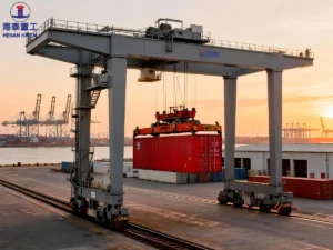
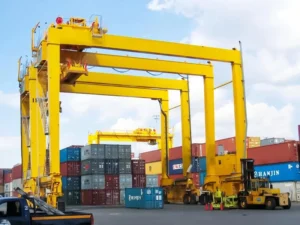
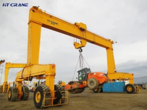
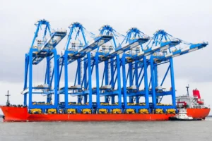
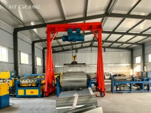
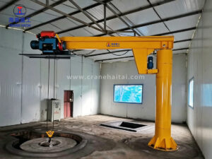
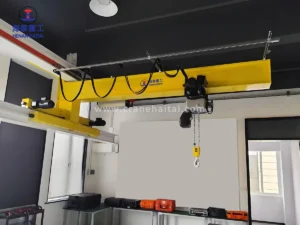
Procurement teams often focus on crane capacity and span during the specification process and treat the electrical system as a secondary item. In practice, the drive system directly determines cycle efficiency, positioning accuracy, energy consumption, and long-term maintenance cost. For high-duty applications — steel mill cranes, RTG cranes, ship-to-shore cranes — the electrical system is no less important than the structure itself.
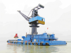
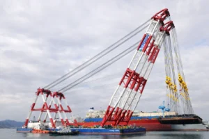
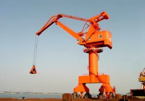
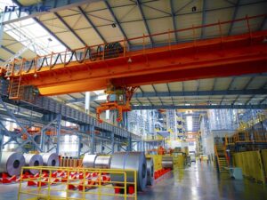
For overhead cranes, gantry cranes, container cranes, marine boat cranes, and port cranes, the mechanical structure determines the load-bearing capacity, whilst the crane motor, variable frequency drive and control system determine the operation of the equipment.
In practical projects, many crane failures do not stem from the steel structure or gearboxes, but rather from the inappropriate selection of drive systems. For example, issues such as crane motors operating under prolonged overload, insufficient inverter capacity, and inadequate control logic design can all lead to frequent equipment downtime, increased maintenance costs, and even safety incidents.
So, how can you select crane motors, VFD inverters and control systems?
Introduction to HT Crane Drive System Selection Guide
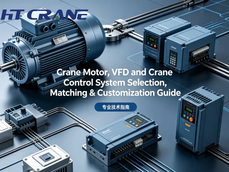
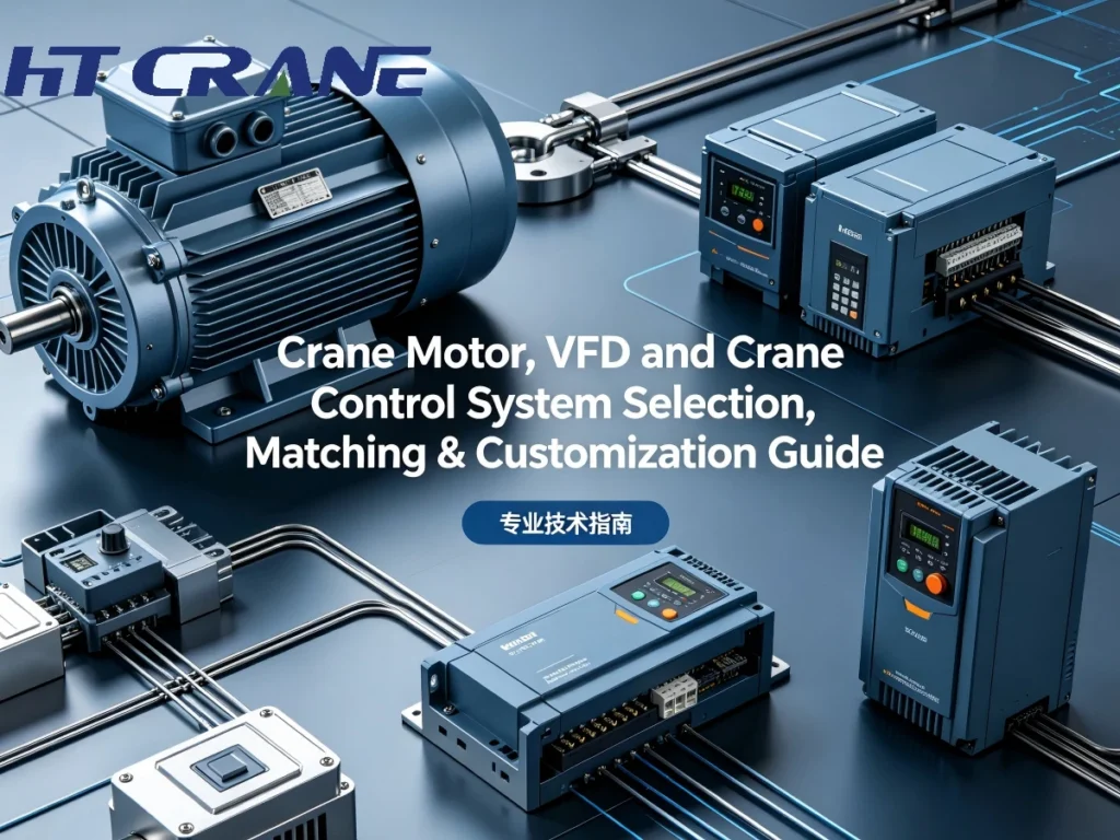
This guide covers the three core components of a crane electrical drive system: the crane motor, the frequency converter (variable frequency drive, VFD), and the control system (PLC-based control cabinet).
The electrical drive system is the key system of any industrial crane. A mismatched crane motor, an undersized VFD, or a poorly configured control cabinet will compromise performance, shorten component lifespan, and create safety risk — regardless of how well the structural steel is designed.
The guide provides a detailed explanation of the working principles, selection criteria, matching logic and customisation options for these components, and illustrates how Haitai Crane’s integrated electrical solutions comprehensively meet the requirements of various industrial and port crane applications.
Part 1: Crane Motors — Types, Selection, and Key Parameters
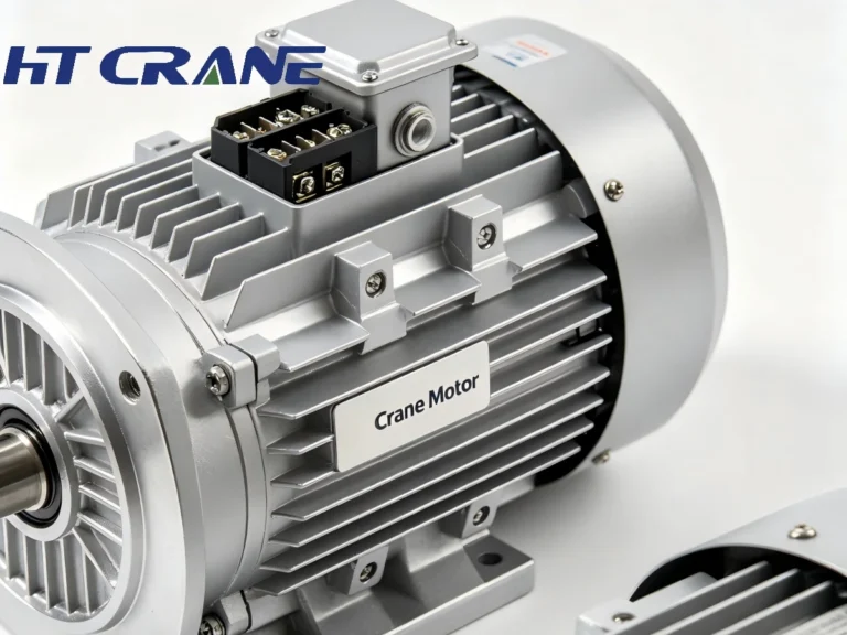
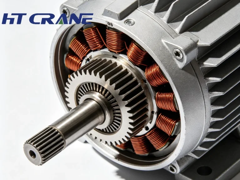
A crane motor must deliver torque on demand across a wide speed range, handle frequent starts and stops without overheating, and survive the mechanical vibration and thermal cycling that characterize industrial crane operation. These requirements distinguish crane-duty motors from standard industrial motors in both design and specification.
Main Crane Motor Types
| Motor Type | Operating Principle | Typical Application | Key Advantage |
| AC Squirrel Cage Induction Motor | Rotating magnetic field induces rotor current | General overhead cranes, hoists | Robust, low maintenance, low cost |
| AC Wound Rotor (Slip Ring) Motor | External rotor resistance controls speed/torque | Heavy-duty hoists, steel mill cranes | High starting torque, smooth speed control |
| AC Variable Frequency Motor | Standard induction motor matched to VFD | Modern cranes with VFD drives | Precise speed control, energy efficient |
| DC Motor (legacy) | Commutator and brush assembly | Older installations | Wide speed range — largely superseded by VFD+AC |
| Permanent Magnet Synchronous Motor (PMSM) | Permanent magnet rotor, no slip | Precision hoists, compact drives | High efficiency, compact, full torque at zero speed |
Source: IEC 60034-1:2022 (Rotating Electrical Machines); crane motor classification per FEM 9.682 and IEC 60034-12. Data reflects standard industrial crane motor types as of 2024.
Critical Selection Parameters
Duty Class (S-rating): IEC 60034-1 defines motor duty cycles from S1 (continuous) to S9 (non-periodic). Crane hoist motors typically operate under S3 (intermittent periodic) or S4 (intermittent periodic with starting). Specifying the wrong duty class leads to thermal overload and premature winding failure. The motor’s cyclic duration factor (CDF) — the ratio of working time to total cycle time — must match actual operating patterns.
Insulation Class: Class F insulation (155°C maximum winding temperature) is the standard minimum for crane motors in industrial environments. Class H (180°C) is specified for steel mill and foundry applications where ambient temperature and heat radiation are elevated. Insulation class directly determines motor lifespan under thermal load.
Protection Rating (IP Code): IP55 is standard for enclosed industrial crane environments (dust-protected, jet-proof). IP65 or higher is required for outdoor cranes, port environments, and wash-down applications. IP rating is specified per IEC 60529.
Starting Torque and Locked Rotor Torque: Crane motors must produce sufficient torque to accelerate rated load from standstill, often against gravity. Starting torque of 200–300% of rated torque is typical for hoist duty. Undersized starting torque causes stalled starts and mechanical shock loads on the hoist mechanism.
Thermal Capacity and Cooling: Crane motors in high-cycle applications accumulate heat rapidly. Forced cooling (separately powered ventilation fan) is standard on crane-duty motors above 15 kW. Self-cooled (IC411) motors are acceptable for light-duty applications only.
Reference Table for Common Hoisting Motors
| Lifting Capacity | Duty Class | Recommended Motor Power | Recommended Type |
|---|---|---|---|
| 3T | A3-A4 | 4kW-5.5kW | Tapered rotor motor |
| 5T | A4-A5 | 7.5kW | Motor designed for variable frequency drives |
| 10T | A5 | 11kW-15kW | YZR Hoisting Motor |
| 16T | A5-A6 | 18.5kW | YZR Hoisting Motor |
| 20T | A6 | 22kW-30kW | Variable Frequency Hoisting Motor |
| 32T | A6-A7 | 37kW | Metallurgical-Grade Motor |
| 50T | A7-A8 | 55kW and above | Customized Solution |
Please note: For a 20-ton overhead or gantry crane with lifting speeds of 5 m/min and 10 m/min respectively, the motor power may differ by up to 40%.
Haitai Crane Motor Offering
Haitai Crane supplies crane-specific AC motors across the full range of overhead crane, gantry crane, RTG crane, and ship-to-shore crane applications. Standard offerings include:
- YZR series wound rotor motors (7.5 kW – 200 kW) for heavy-duty hoist and travel applications requiring high starting torque
- YZ series squirrel cage motors for standard duty workshop overhead cranes and light industrial applications
- VFD-matched AC induction motors optimized for variable frequency drive operation (Class F/H insulation, encoder-ready)
- Custom motor specifications available for extreme environments: high-temperature (steel mill/foundry), marine-grade (port cranes), explosion-proof (hazardous area classification)
Haitai Crane’s motor selection process starts with the application duty class and actual operating cycle — not nominal power rating. This ensures motor thermal capacity is matched to real-world load patterns, not theoretical maximums.
Part 2: Frequency Converters (VFDs) — Selection, Matching, and Benefits
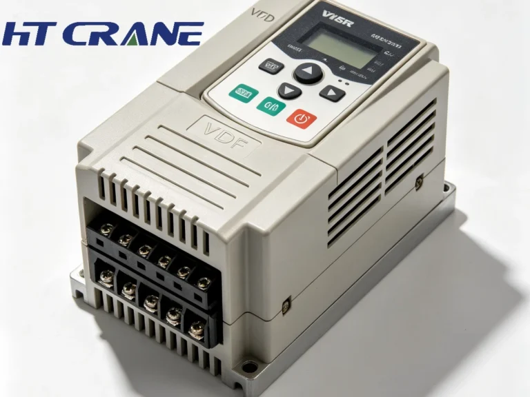
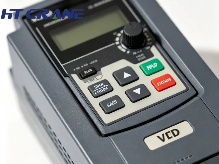
A frequency converter — also called a variable frequency drive (VFD) or inverter — controls AC motor speed and torque by varying the frequency and voltage of the power supply. For crane applications, VFDs have replaced traditional contactor-resistor speed control systems in most modern installations, delivering significant advantages in performance, energy efficiency, and mechanical longevity.
Why VFDs Matter for Crane Performance
| Performance Factor | Contactor / Resistor Control | VFD Control | Improvement |
| Speed control | Step-change (2–5 fixed speeds) | Continuously variable (0–100%) | Smooth, precise positioning |
| Starting current | 600–800% of rated current | 100–150% of rated current | Reduced grid impact |
| Mechanical shock | High (step changes) | Low (ramped acceleration) | Extended mechanical life |
| Energy consumption | Resistor dissipates braking energy | Regenerative option available | 15–30% energy saving |
| Brake wear | High (mechanical braking frequent) | Low (electrical braking primary) | Extended brake life |
| Positioning accuracy | Limited by speed steps | Sub-millimeter with encoder | Precision load placement |
Source: Energy savings data per VFD manufacturer published case studies (ABB, Siemens, Schneider Electric, 2021–2023); performance comparison based on IEC 61800 series drive standards.
VFD Selection Parameters for Crane Applications
Continuous Output Current Rating: The VFD must be sized for the motor’s rated current plus a derating margin for the duty cycle and ambient temperature. For crane applications with frequent starts, a minimum 10–20% current margin above motor rated current is standard practice. Undersized VFDs trip on overcurrent during acceleration peaks.
Overload Capacity: Crane drives require 150% overload capacity for 60 seconds (Heavy Duty, HD rating) as a minimum — not the standard 110% Light Duty (LD) rating. Verify that the VFD is specified for crane-duty (HD) operation, not general industrial use.
Braking Resistor and Regenerative Braking: Lowering a loaded hook generates energy that must be dissipated. Standard VFDs use a braking resistor (dynamic braking); regenerative VFDs return this energy to the supply grid. For high-duty cranes making frequent loaded lowering movements — ship-to-shore, steel mill ladle cranes — regenerative drives achieve 20–30% net energy reduction and eliminate braking resistor maintenance.
Anti-Sway and Load Control Functions: Modern crane VFDs include built-in anti-sway algorithms (pendulum damping for trolley movement), soft start/stop curves, load torque memory, and slack rope detection. These functions are configured in the VFD parameters rather than added as external components, significantly simplifying the control system.
Communication Protocol: Integration with PLC-based crane control systems requires a compatible communication interface. PROFIBUS, PROFINET, EtherNet/IP, and CANopen are the most common protocols. Confirm protocol compatibility between VFD and PLC brands before procurement.
Reference Table of FDV Selection
| Motor Power | Recommended FDV Capacity | Control Method |
|---|---|---|
| 4kW | 5.5kW | V/F control |
| 7.5kW | 11kW | Vector control |
| 11kW | 15kW | Vector control |
| 15kW | 18.5kW | Vector control |
| 22kW | 30kW | Closed-loop vector control |
| 30kW | 37kW | Closed-loop vector control |
| 37kW | 45kW | Closed-loop vector control |
| 55kW | 75kW | Heavy-duty closed-loop vector control |
VFD Brands and Haitai Crane’s Approach
Haitai Crane integrates VFDs from leading global manufacturers including ABB (ACS880 crane drive series), Siemens (SINAMICS G/S series), Schneider Electric (Altivar Process series), and Yaskawa. Selection is application-driven:
- ABB ACS880 with DriveAP crane application package: standard specification for heavy-duty overhead and gantry cranes requiring integrated anti-sway and hoist control
- Siemens SINAMICS S120: preferred for high-precision applications and automation-integrated systems (TIA Portal PLC environment)
- Domestic VFD brands (Inovance, INVT): cost-competitive option for standard duty workshop cranes where total cost of ownership is the primary procurement driver
Haitai Crane’s electrical engineering team performs VFD-motor matching calculations for every project, including thermal derating at site ambient temperature, overload verification against the actual duty cycle, and braking energy calculation to size the braking resistor or confirm regenerative drive requirement.
Part 3: Crane Control Systems — PLC, Logic, and Cabinet Design
The crane control system integrates the motor drives, safety functions, operator interface, and (where applicable) automation systems into a coordinated operating platform. For modern industrial cranes, PLC-based control has replaced relay logic as the standard architecture, offering programming flexibility, diagnostic capability, and communication integration that relay systems cannot provide.
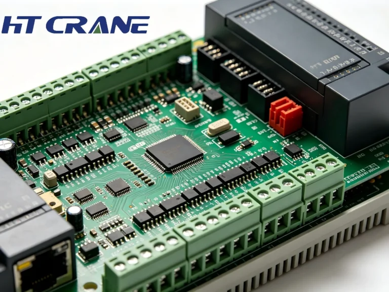
Control System Architecture
PLC (Programmable Logic Controller): The PLC executes the crane’s operating logic: motion sequencing, interlock management, fault detection, and communication with drives and operator interfaces. Industrial crane PLCs must be rated for the ambient conditions of the crane environment — vibration, temperature range, and electromagnetic interference from VFD switching are the primary concerns. Leading PLC platforms used in crane applications include Siemens S7-300/400/1200/1500, Allen-Bradley (Rockwell), and Mitsubishi FX/Q series.
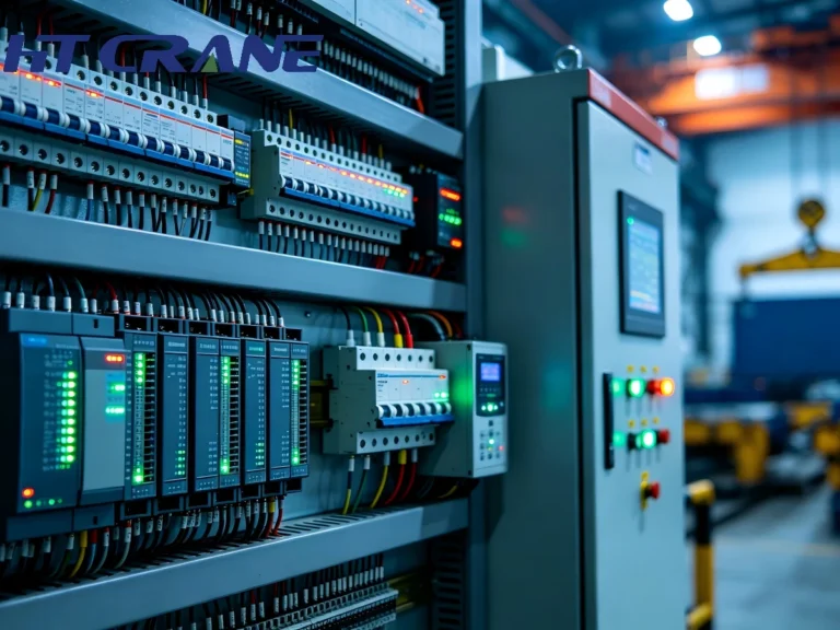
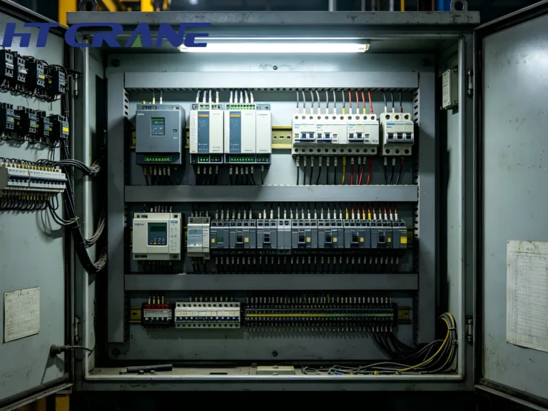
Control Cabinet (MCC / Crane Panel): The main control cabinet houses the PLC, VFD units, main circuit breakers, contactors, protection relays, and terminal blocks. Cabinet design must address thermal management (VFDs generate significant heat), cable segregation (power and signal cables must be separated to prevent interference), and IP rating appropriate to the installation environment. A poorly designed cabinet is one of the most common sources of recurring crane electrical faults.
Operator Interface: Crane operator interfaces range from push-button pendants (simple, robust, lowest cost) to radio remote controls (mobility, safety distance from load) to cabin-mounted HMI touchscreens (full diagnostic display, parameter adjustment). For automated cranes, the operator interface becomes a monitoring and intervention console rather than a primary control device.
Safety Circuit (SIL / Category): Crane safety functions — hoist overload protection, end-of-travel limits, emergency stop, anti-collision — must be implemented in a safety-rated circuit separate from the standard PLC logic. EN ISO 13849-1 defines Performance Level (PL) requirements; IEC 62061 defines Safety Integrity Level (SIL) requirements. For cranes handling molten metal, hazardous materials, or operating in populated areas, SIL 2 or PLd/PLe safety circuit implementation is typically mandatory.
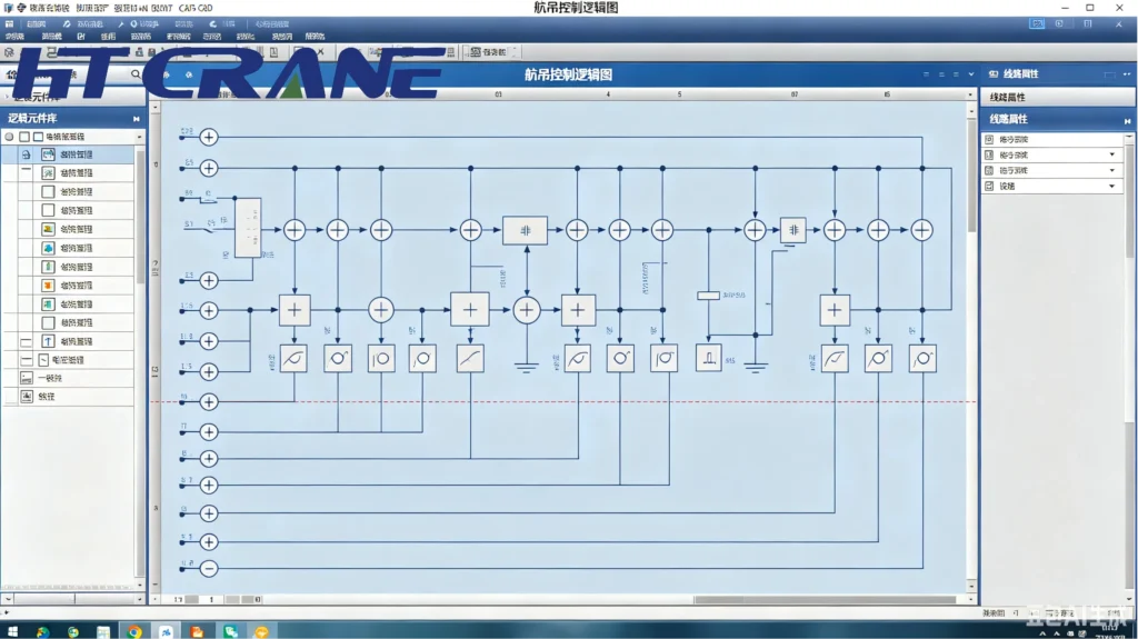
Control System Customization Options
| Function | Standard Scope | Haitai Custom Option | Typical Application |
| Speed profiles | Fixed acceleration/deceleration ramps | Multi-zone speed mapping (slow approach zones, creep speed at limits) | Precision assembly, mold handling |
| Load weighing | Overload cutoff only | Real-time load display, load logging, production data integration | Foundry, steel mill, logistics |
| Anti-sway control | Basic ramp control | Active pendulum damping algorithm (VFD-integrated or external) | Long span cranes, automated terminals |
| Tandem operation | Single crane control | Master-slave synchronization for multi-crane lifts | Large casting handling, ship blocks |
| Remote monitoring | Local fault indicator | SCADA integration, SMS/email fault alerts, remote parameter access | Unstaffed or multi-site operations |
| Automation integration | Manual operator control | PLC handshake with WMS/TOS, AGV interface, barcode/RFID positioning | Automated warehouse, port terminal |
Source: Haitai Crane engineering specifications, 2024. Custom options subject to project scope confirmation.
Comparison of Different Control Methods
| Control Method | Accuracy | Cost | Suitable Applications |
|---|---|---|---|
| V/F Control | Low | Low | Small-ton cranes |
| Open-loop Vector Control | Medium | Medium | Standard overhead cranes |
| Closed-loop Vector Control | High | High | Port cranes, Maine Boat Crane |
| Servo Control | Extremely high | Highest | Automated warehousing |
Current mainstream solutions on the market: Overhead cranes typically employ open-loop or closed-loop vector control. Automated projects are gradually adopting servo systems.
Haitai Crane Control System Standards
Haitai Crane’s control systems are designed and assembled to the following standards as baseline:
- IEC 60204-32:2023 — Safety of Machinery: Electrical Equipment of Hoisting Machines (primary crane electrical standard)
- EN ISO 13849-1:2023 — Safety of Machinery: Safety-Related Parts of Control Systems (Performance Level assessment)
- IEC 61800-5-2 — Adjustable Speed Electrical Power Drive Systems: Safety requirements (drive-integrated safety functions)
- CE marking per Machinery Directive 2006/42/EC for export to European markets
- GB/T 14048 series (China national standard for low-voltage switchgear) for domestic supply
All Haitai Crane control cabinets undergo factory acceptance testing (FAT) before shipment, including functional simulation of all motion axes, safety circuit verification, and communication protocol testing. FAT documentation is provided as a standard contract deliverable.
Part 4: System Integration — Matching Motor, VFD, and Control System
A motor, VFD, and control system from different suppliers, independently specified, is not an integrated drive system. The performance of the complete system depends on how well these three components are matched — in power ratings, communication interfaces, safety architecture, and software configuration. This integration work is where many crane electrical systems fail in practice.
The Matching Logic: Three Variables, One System
Motor-to-VFD power matching: The VFD continuous output kVA rating must cover the motor’s rated power at the lowest expected power factor. For crane hoist motors with frequent short-duration overloads, the VFD must be sized for the peak demand (typically 150% of rated for 60 seconds), not just the continuous rating. A VFD sized at exactly motor rated power will trip during normal acceleration peaks.
VFD-to-control communication: The VFD must receive speed reference, direction, and enable signals from the PLC, and must return actual speed, current, fault status, and torque feedback. Mapping these signals correctly — including scaling and addressing — is a commissioning-critical task. Incorrect signal scaling is a common source of unexpected crane behavior during startup.
Safety circuit integration: Emergency stop, overload cutoff, and end-of-travel limits must act at the drive level (disabling VFD output), not just at the control circuit level. If a safety function only opens a contactor upstream of the VFD, regenerative energy from a moving load may still drive the motor — a potentially dangerous condition on hoist axes.
Common Integration Failures and How to Avoid Them?
| Failure Mode | Root Cause | Prevention |
| VFD overcurrent trip on start | VFD undersized for peak starting current | Size VFD at HD (150% overload) rating, not LD |
| Motor thermal overload | Duty class mismatch (S1 motor in S3/S4 application) | Specify motor CDF ≥ actual application CDF |
| Erratic speed behavior | VFD-PLC signal scaling error | Verify analog reference scaling at commissioning; use digital fieldbus where possible |
| E-stop fails to stop load descent | Safety circuit only disconnects upstream power | Configure VFD Safe Torque Off (STO) function as primary safety response |
| Persistent ground fault alarms | Power/signal cable routing in same conduit | Segregate VFD power cables from control signal cables by minimum 200mm or screen |
| Control cabinet overheating | VFD heat dissipation not accounted in cabinet design | Size cabinet cooling based on total VFD power loss (typically 3–5% of drive rated power) |
Source: Haitai Crane field service records and commissioning data, 2021–2024. Failure modes represent common findings in third-party crane electrical system assessments.
Part 5: Application-Specific Configurations
Workshop Overhead Crane (5–50ton, Standard Duty)
For standard workshop overhead cranes in the 5–50 ton range at A4–A5 duty class, Haitai Crane’s standard electrical package includes: YZ/YZR series motor, Inovance or INVT VFD with crane-duty parameter set, Siemens S7-1200 PLC, IP54 control cabinet, and radio pendant control. This configuration covers the large majority of manufacturing, fabrication, and assembly workshop applications at competitive cost.
Heavy-Duty Industrial Crane (50ton+, Foundry / Steel Mill)
Heavy-duty cranes at A6–A8 duty in steel mill and foundry environments require: high-temperature Class H insulated motors with forced cooling, ABB ACS880 or Siemens SINAMICS VFDs with regenerative braking, SIL 2 rated safety circuit for hoist axis (ladle handling requirement), IP65 control cabinet with active cooling, and fiber optic communication links between ground-level control and crane-mounted panels. Haitai Crane’s heavy industrial configuration has been deployed on casting bridge cranes up to 320t at A8 duty.
RTG Crane Electrical System
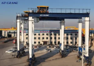
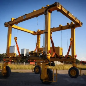
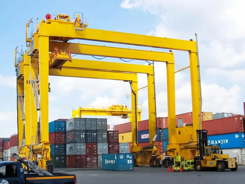
Rubber Tired Gantry crane electrical systems present unique challenges: the drive system must manage four independent gantry travel drives (8–16 wheel motors), a hoist drive, and a trolley drive — all coordinated by a central PLC. Haitai Crane’s RTG electrical package includes multi-axis VFD coordination with load sharing algorithms for the travel drives, integrated anti-sway for the trolley, and pre-wired cable reel interface for E-RTG shore power connection. Remote monitoring via cellular or WiFi is standard for RTG fleet applications.
Port and Ship-to-Shore Crane Electrical Systems
STS crane electrical systems operate at the largest scale — hoist motors of 200–500 kW, regenerative multi-quadrant drives, dual hoist for tandem lift, and integration with terminal operating system (TOS) for semi-automated or automated operation. Haitai Crane’s STS electrical solutions are engineered to IEC 60204-32 and PIANC terminal infrastructure standards, with full FAT and site acceptance testing (SAT) protocols as standard deliverables.
Summary: Why Integrated Electrical System Design Matters?
The motor, frequency converter, and control system of a crane are not independent components — they are a matched system. A mismatched drive system creates operational problems that no amount of structural or mechanical quality can compensate for. Correct specification of duty class, thermal capacity, VFD overload rating, safety circuit architecture, and system communication is the foundation of a crane that performs at its rated capability throughout its service life.
Haitai Crane’s electrical engineering approach: integrated design from motor selection through VFD sizing to control cabinet assembly and factory acceptance testing. Every electrical system is engineered to the application’s actual duty cycle, ambient conditions, and safety requirements — not to a generic catalogue specification.
For procurement teams: request the motor duty class calculation, VFD sizing worksheet, and safety circuit Performance Level assessment as standard deliverables from any crane supplier. These documents confirm that the electrical system has been engineered to your application, not simply assembled from stock components.
Frequently Asked Questions
Q1: What is the difference between a crane-duty motor and a standard industrial motor?
Crane-duty motors are for intermittent, high-cycle operation with frequent starts, stops, and reversals under load, which would overheat a standard continuous-duty motor quickly. Key differences are:
- higher thermal capacity (Class F or H insulation as standard)
- wound or VFD-optimized rotor design for controlled starting torque
- reinforced bearings for shaft loading from wire rope pull
- duty class rating (S3/S4 per IEC 60034-1)
Substituting a standard motor in a crane application is a common source of premature motor failure.
Q2: How do I size a frequency converter (VFD) for a crane hoist application?
VFD sizing for crane hoists requires three calculations:
- (1) continuous output current must exceed motor rated current with a 10–20% margin;
- (2) overload capacity must be confirmed at 150% for 60 seconds (Heavy Duty rating); most general-purpose VFDs are rated only 110% overload (Light Duty) and will trip on crane duty;
- (3) braking energy during loaded lowering must be calculated to size the braking resistor or determine whether regenerative braking is warranted.
For hoists above 30 kW with frequent full-load lowering cycles, regenerative drives typically provide payback within 3–5 years through energy savings and eliminated braking resistor maintenance.
Q3: What PLC platform does Haitai Crane use for crane control systems?
Haitai Crane primarily uses Siemens S7-1200 and S7-1500 series PLCs for new crane control systems. Allen-Bradley (Rockwell) and Mitsubishi platforms are available for projects requiring specific brand compatibility. The PLC platform choice is secondary to the quality of the application programming — Haitai’s control engineers program all crane-specific logic (motion profiles, safety interlocks, drive communication, fault management) in-house and provide full source code as a standard contract deliverable. Customers who require third-party PLCs can specify their preferred platform at order.
Q4: Can Haitai Crane retrofit a VFD drive system to an existing older crane?
Yes, drive system retrofit is a standard service offered by Haitai Crane. A typical retrofit involves:
- assessment of existing motor condition
- duty class suitability (motor replacement may be required if wound rotor motors are being replaced with VFD-matched units)
- VFD selection and sizing based on motor parameters and application duty
- control cabinet modification or replacement to accommodate VFD and updated PLC;
- safety circuit upgrade to current standards (EN ISO 13849-1 Performance Level assessment)
Retrofits can typically save 15–30% energy, significantly extend motor and brake lifespan, and improve positioning. Haitai Crane provides a pre-retrofit technical assessment report before any commitment to project scope.
Q5: What documentation does Haitai Crane provide with an electrical drive system?
Standard documentation package includes:
- electrical schematics (single-line diagram, control circuit drawings, cabinet layout)
- motor data sheets with duty class and thermal calculations
- VFD parameter listing and commissioning record
- PLC program source code with function block documentation
- safety circuit Performance Level assessment (EN ISO 13849-1)
- factory acceptance test (FAT) report with test results for all motion axes and safety functions
- operation and maintenance manual
For export projects, CE Declaration of Conformity and Machinery Directive technical file are included. All documentation is provided in English as standard; Chinese, Spanish, Russian, Arabic and other-language versions are available on request.
Related Standards & References
- IEC 60034-1:2022 – Rotating Electrical Machines: Rating and Performance
- IEC 60204-32:2023 – Safety of Machinery: Electrical Equipment of Hoisting Machines
- IEC 61800-5-2:2016 – Adjustable Speed Drive Systems: Safety requirements
- EN ISO 13849-1:2023 – Safety of Machinery: Safety-Related Parts of Control Systems
- IEC 60529:2013 – Degrees of Protection Provided by Enclosures (IP Code)
- FEM 9.682 – Classification of Crane Mechanisms
- ISO 4301-1:2016 – Cranes: Classification, General
- Machinery Directive 2006/42/EC (EU)
For technical enquiries, application-specific motor and VFD selection, or control system customization requirements, contact Haitai Crane’s electrical engineering team. Project-specific technical proposals include duty class calculations, VFD sizing worksheets, and safety circuit PL assessment at no charge for qualified procurement projects.