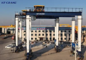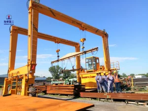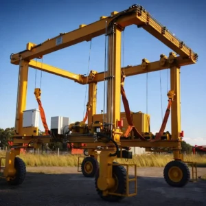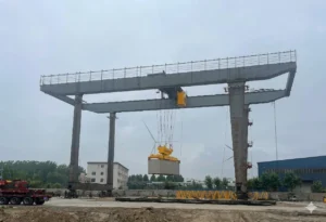
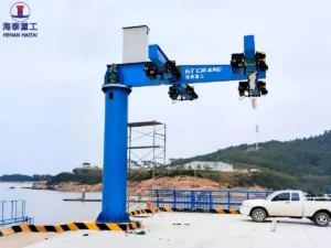
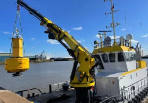
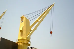
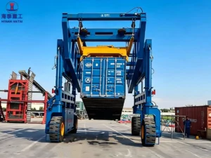
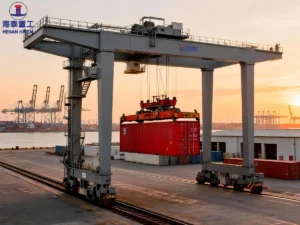
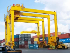
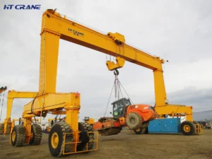
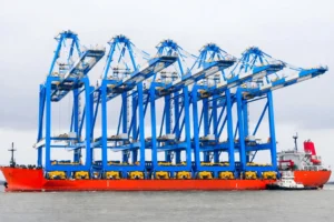
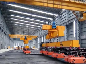
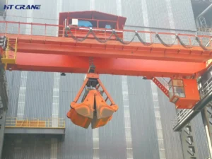
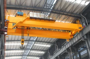
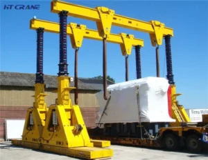
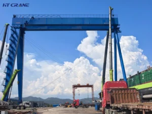
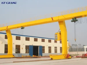
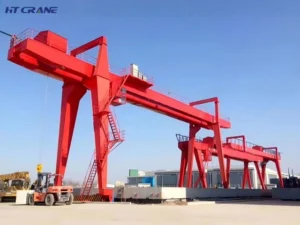
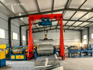
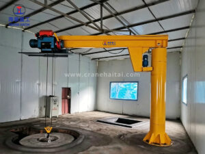
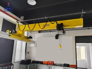
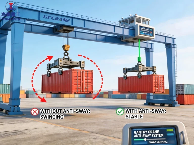
Load swing is not just an annoyance. On long-span overhead and gantry cranes, it delays cycle completion, increases structural fatigue, and creates collision risk with adjacent equipment or personnel. Crane anti-sway systems — ranging from VFD-integrated pendulum damping algorithms to closed-loop encoder feedback — actively counteract swing during acceleration and deceleration. The anti-sway system can reduce residual sway by 80–95% in controlled applications. This guide explains the physics, the technology, and how to choose the right approach for your crane and duty cycle.
Why Crane Operators Need Crane Anti-Sway Systems?
All crane operators face the issue that after the trolley stops, the load will keep swinging due to inertia, and the swing will gradually weaken until it stops. For short-span light loads, this process only takes a few seconds, but for a 30-meter gantry crane with a 20-ton load suspended by a 12-meter rope, the swing period can exceed 6 seconds, and the remaining swing can last for more than half a minute. During this period, the crane cannot unload the load safely, cannot start the next work cycle, and the load moves unpredictably in the working area.
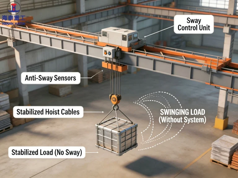
Anti-sway technology solves this problem directly. Instead of waiting for the swing to subside naturally, it controls the crane’s driving system to actively suppress the oscillation when accelerating and decelerating. As a result, when the load reaches the destination, the swing is almost zero and can be landed immediately. For production cranes in steel mills, port terminals and automatic warehouses, this is not a convenient function, but a requirement for work cycle time and safety.
The Physics of Load Swing: Why Does It Happen?
A suspended crane load is equivalent to a simple pendulum. The physics is classical: when the trolley accelerates, inertia causes the load lag, forming a swing angle. When the trolley decelerates or stops, momentum makes the load move forward beyond the position of the trolley, and starts to oscillate. The swing period — the time for one complete back-and-forth cycle — mainly depends on one variable: rope length.
The Pendulum Period Formula
Swing period (T) = 2π × √(L / g)
Where: T = period in seconds, L = rope length in metres, g = 9.81 m/s²
Examples: L = 3 m → T ≈ 3.5 s | L = 6 m → T ≈ 4.9 s | L = 12 m → T ≈ 6.9 s
The critical implication: as the rope length increases, the swing period increases, and the longer the period, the slower the natural attenuation of the swing. The swing cycle of a 12-meter rope is nearly twice that of a 3-meter rope, and the residual oscillation after the trolley stops is also more lasting. Therefore, high-bay warehouses with long rope lengths are most seriously affected by uncontrolled load swing.
In addition, the traveling speed and acceleration rate of the trolley will also affect the maximum swing angle during movement. Higher acceleration required for fast cycle times will produce a larger initial swing angle. Without active compensation, fast cranes and long ropes are fundamentally contradictory: the speed required for productivity produces swing that hinders efficient work.
How Haitai Crane Anti-Sway Systems Work: The Three Main Approaches
Crane anti-sway systems address load swing through three different mechanisms: input shaping, active feedback control, and mechanical damping. Modern systems often combine two or all three methods. Understanding these three methods helps you evaluate the solutions provided by crane suppliers.
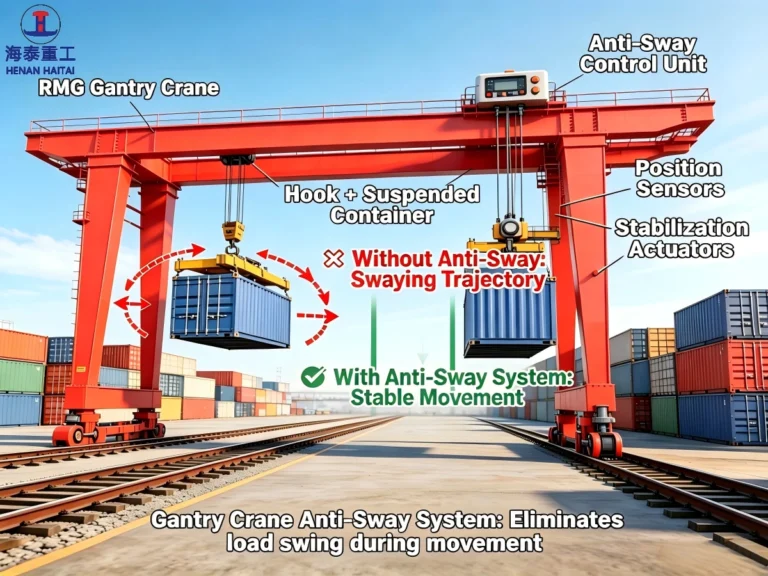
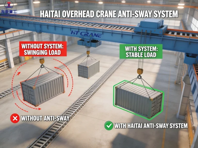
Approach 1: Input Shaping (Open-Loop Anti-Sway)
Input shaping is the most widely used anti-sway method in industrial crane drives. Instead of measuring swing and then reacting to it, input shaping modifies the trolley acceleration command before sending it to the drive, adjusts the motion profile, and cancels the oscillations generated by each acceleration.
The key insight: every acceleration command will create a swing. If the second acceleration command is accurately timed, that is, half of the pendulum period after the first acceleration, the second swing has the same amplitude and opposite phase to the first swing, and the two cancel each other. Finally, after the movement is completed, the residual swing is close to zero.
Input shaping needs to know the accurate rope length to calculate the pendulum period, but does not require real-time sensor feedback. It is completely implemented by software within the VFD or PLC, and does not need to add additional hardware to the crane. Most major variable frequency drive manufacturers include input shaping algorithms in their crane application packages. ABB (DriveAP), Siemens (SINAMICS crane function), Konecranes’ proprietary driving software, and Haitai Crane’s own frequency converter parameter configuration all have different versions of this method.
Approach 2: Closed-Loop Feedback Control (Active Anti-Sway)
Closed-loop crane anti-sway systems measure the actual swing angle in real time and generate corrected trolley motion commands to offset the oscillation. A sensor is typically with an accelerometer mounted on the hoist, or a camera-based vision system tracking the load or rope angle. The sensor provides continuous swing angle feedback to the control system, which commands the trolley drive to counteract the measured swing.
Closed-loop systems are more robust than open-loop input shaping because they respond to external swing (from wind gusts, load impact, or uneven rope threading) that input shaping cannot anticipate. They can also adapt automatically to rope length changes without requiring manual parameter adjustment. The tradeoff is the increase in hardware cost and complexity: sensors, feedback loops, and tuning work that input shaping does not require.
Closed-loop anti-sway is standard specification on ship-to-shore (STS) container cranes and high-speed automated storage and retrieval systems. In these scenarios, external interference (wind, vessel motion, high trolley speed) makes the open-loop method insufficient.
Approach 3: Mechanical Damping
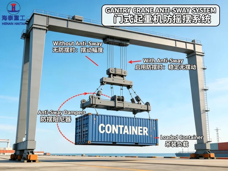
Mechanical damping systems reduce swing through physical constraint, typically through a rigid or semi-rigid connection between the trolley and the lifting device, limiting the swing angle of the load relative to the trolley. Tagline and guide rope systems are the simplest form. Spreader guidance systems on container cranes combine rope reeving geometry and rigid headblock frames to limit spreader rotation and swing of spreaders.
Mechanical damping is effective, but it sacrifices flexibility for anti-sway control. will not swing, but it cannot adapt to the load positioning tolerance that requires a certain degree of horizontal flexibility. Therefore, mechanical damping is most often used as a supplement to active systems. For example, the spreader head frame mechanically limits the roll and pitch, while the active anti-sway algorithm controls the longitudinal and lateral swing.
| Approach of Crane Anti-sway Systems | Mechanism | Sensor Required | External Swing Rejection | Aplicação típica |
|---|---|---|---|---|
| Input Shaping (Open-Loop) | Shaped acceleration profile cancels induced oscillation | No — uses calculated rope length | Não | Standard workshop and production cranes; most VFD platforms |
| Closed-Loop Feedback | Real-time swing measurement drives corrective trolley motion | Yes — accelerometer or camera | Sim | STS cranes, high-speed automation, wind-exposed installations |
| Mechanical Damping | Physical constraint limits maximum swing angle | Não | Partial | Container spreaders, guided hoist systems, tagline operations |
| Combined (Active + Shaping) | Input shaping minimises induced swing; feedback corrects residual and external swing | Sim | Sim | Automated port terminals, precision industrial cranes |
Source: Anti-sway technology classification based on published drive application documentation from ABB (ACS880 DriveAP), Siemens (SINAMICS S120 crane application), and academic literature on crane control systems. Data reflects industrial crane practice as of 2026.
VFD-Integrated Crane Anti-Sway Systems: How It Works in Practice?
The most common anti-sway implementation on industrial overhead cranes and gantry cranes is the VFD-integrated input shaping algorithm. It is built into the frequency converter’s crane application software and configured through the drive’s parameter interface. Understanding how this works in practice helps procurement and engineering teams evaluate supplier claims and commissioning procedures.
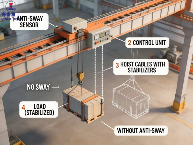
The Parameter Configuration Process
When a VFD-integrated crane anti-sway system is commissioned, the crane engineer enters the rope length (or the range of rope lengths if the crane operates at multiple hoist heights) into the drive’s anti-sway parameter set. The drive calculates the pendulum period from this value and uses it to shape the acceleration and deceleration ramp profiles of the trolley drive. No physical sensor is required.
On cranes where lift height varies significantly during operation, for example, a 10-meter lift height range on a steel mill crane. Some systems accept a continuous rope length input from a hoist encoder, updating the anti-sway period calculation in real time as the hook height changes. More basic systems use a fixed representative rope length (typically mid-range) and accept some degradation of anti-sway performance at the extremes of the height range.
Good Performance of HT Crane Anti-Sway Systems
A correctly configured VFD anti-sway system on a standard overhead crane should achieve residual swing angles below 0.5° after trolley stop in controlled indoor conditions. Published performance data from major drive suppliers indicates 80–95% reduction in residual sway compared to uncontrolled operation under equivalent travel distance and speed conditions. Cycle time improvements of 15–30% are typical — the crane can begin the landing phase immediately after trolley stop, rather than waiting for natural decay.
Performance note: VFD input shaping anti-sway performance degrades when rope length is inaccurately set, when the crane structure has significant lateral flexibility (long-span single girder cranes). When external disturbances (wind, load impact) introduce swing that was not present in the commanded motion. Closed-loop feedback is the correct choice where any of these conditions apply.
HT Crane’s VFD Crane Anti-Sway Systems Implementation
Haitai Crane configures anti-sway function as standard on all cranes equipped with ABB ACS880 (DriveAP crane application package), Siemens SINAMICS, and Inovance MD810 series drives. The commissioning procedure includes:
- Rope length entry and pendulum period calculation
- Travel speed and acceleration ramp optimisation for the anti-sway profile
- Test lifts at rated load across the full travel range to verify residual swing performance
- Parameter record in the Factory Acceptance Test (FAT) documentation
For applications requiring closed-loop performance like long-span cranes, outdoor RTG installations, precision automated systems, Haitai’s engineering team integrates accelerometer-based feedback modules or vision system inputs in addition to the drive-level input shaping.Then the crane anti-sway systems will provide active swing rejection for externally induced oscillations.
Quantifying the Impact: What HT Crane Anti-Sway Systems Delivers?
Cycle Time
Load swing extends cycle time because cranes can not land swinging loads safely. For example, an operator waiting for natural swing decay on a 12-meter rope may spend 20 to 40 seconds per cycle, which translates to 10 to 20 minutes of idle time per hour per crane at 30 cycles per hour. Anti-sway systems can reduce residual swing to near zero when the trolley stops, thus recovering most of this time. Published data from high-duty RTG crane installations shows that after retrofitting with an anti-sway system, the number of gross moves per hour increased by 15 to 25% when all other variables remain unchanged.
Structural Fatigue
Uncontrolled load swing applies dynamic loads to the crane structure every time the load reaches the end of its swing arc and reverses direction. Different from static loads, these loads involve rapid direction changes that count as fatigue cycles for structural design. Although ISO 4301-1 crane classification considers dynamic load factors, repeated large-amplitude swing accelerates structural fatigue accumulation beyond design assumptions. Crane anti-sway systems reduce the amplitude of these dynamic load events and extend the service life of the structure.
Safety – Swing Radius
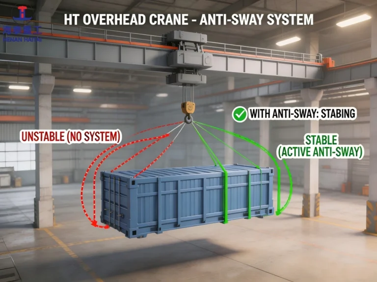
A swinging load is a moving hazard. In places where personnel work near crane operations, like foundries, fabrication shops and maintenance bays, uncontrolled load swing can move heavy loads far beyond the expected drop zone. Crane anti-sway systems reduce the maximum swing angle and keep the load close to vertical when landing, greatly reducing the probability of collision with adjacent equipment or personnel. For cranes that handle molten metal or hazardous materials, crane anti-sway system is not an option for improving productivity, but a necessary safety control measure.
Positioning Accuracy
Precision assembly operations, such as aerospace component fitting, injection mold placement, and precision welding fixture loading, require that loads are placed within a millimeter error range of the target. Natural swing makes this impossible without prolonged waiting or manual load guidance. Anti-sway systems can achieve residual swing of less than 0.5° when the trolley stops, allowing precision placement directly through crane movement without manual intervention. When combined with absolute encoder positioning on the trolley drive, this enables repeatable and semi-automated load placement.
| Benefit with Crane Anti-Sway Systems | Typical Improvement | Application Most Affected | Standard Reference |
|---|---|---|---|
| Cycle time reduction | 15–30% GMPH improvement | Port RTG / STS, production crane | Published RTG performance data, 2021–2023 |
| Structural fatigue | Reduced dynamic load amplitude | Long-span cranes, high-duty A6–A8 | ISO 4301-1 dynamic load factor framework |
| Positioning accuracy | Residual swing < 0.5° at stop | Precision assembly, mould handling | Drive supplier commissioning specifications |
| Safety — swing radius | 80–95% reduction in peak swing | Foundry, chemical, personnel-proximate ops | EN 13001 load case definitions |
Performance figures based on: ABB ACS880 DriveAP published case studies (2022); Konecranes CXT anti-sway performance data (2021); Siemens SINAMICS crane application benchmark data (2023). Actual results vary by crane configuration, rope length, and travel speed.
Selecting the Right Crane Anti-Sway Systems Approach for Your Application
Crane anti-sway system selection follows from four variables: rope length range, travel speed, exposure to external disturbances, and the degree of positioning precision required. The table below maps common crane types to the appropriate crane anti-sway systems approach.
| Tipo de guindaste | Rope Length | Key Challenge | Recommended Anti-Sway Approach |
|---|---|---|---|
| Workshop overhead crane (5–20 t, indoor) | 3–8 m | Moderate swing, indoor, controlled environment | VFD input shaping — standard configuration |
| Production-line overhead crane (A5–A6 duty) | 3–10 m | Cycle time; landing accuracy at speed | VFD input shaping with rope-length tracking |
| Foundry / ladle crane (A7–A8 duty) | 4–12 m | Safety critical; molten metal; A7/A8 fatigue impact | VFD input shaping + closed-loop accelerometer feedback |
| Single girder crane, long span (>22 m) | 4–10 m | Structural lateral flexibility amplifies swing | Closed-loop feedback to compensate structure compliance |
| RTG crane (container yard, outdoor) | 8–15 m | Wind exposure; long rope; high GMPH target | VFD input shaping + closed-loop wind-disturbance rejection |
| Ship-to-Shore (STS) crane | 20–45 m | Very long rope; wind; vessel motion; twin-lift | Full closed-loop + mechanical spreader guidance |
| Automated warehouse crane (ASRS) | 2–15 m | Precision placement; no operator; high cycle rate | Closed-loop feedback + encoder position control |
Source: Anti-sway application guidance from ABB DriveAP application guide (2022); Konecranes technical publications; Haitai Crane engineering specifications. Classification is indicative — project-specific engineering review recommended for safety-critical applications.
Anti-Sway and Automation: The Enabling Technology
Crane anti-sway is not only an independent safety and productivity function, but also a prerequisite for crane automation. Cranes with unpredictable residual load swing cannot achieve automatic landing, because the landing process requires a clear and controlled load position when placing down. That is why all automated crane systems, from automated warehouse stackers to automated RTG cranes in container terminals, take closed-loop anti-sway as a foundational control layer.
The automation dependency works in both directions. As automation systems require higher load position accuracy, anti-sway algorithms have become more advanced, developing from simple ramp shaping to model predictive control (MPC) methods. This method can optimize the whole trolley travel trajectory at the same time, taking into account speed, position accuracy and zero residual swing at arrival. At present, this technology has been commercially applied in high-end automated STS crane systems, and is entering the industrial overhead crane market with the latest generation of crane VFD application software.
Haitai Crane’s engineering note: For customers planning automation integration, whether retrofitting existing cranes or specifying new automated equipment, crane anti-sway systems performance specification should be part of the initial crane brief, not an afterthought. The VFD platform, motor encoder resolution, and control system architecture all affect achievable anti-sway performance. These decisions are effectively locked in at the time of crane procurement.
Resumo
Load swing is a physics problem that every overhead crane faces and every crane operator works around. Crane anti-sway systems transform it from a workflow constraint into a controlled parameter, thus delivering faster cycle times, lower structural fatigue, improved safety margins, and the precision placement accuracy that automated production increasingly demands.
The technology spectrum runs from VFD-integrated input shaping (standard, no sensor hardware, suited to most indoor industrial applications) to closed-loop accelerometer or vision-based feedback control (required for long ropes, outdoor exposure, or automation integration). Choosing the right approach means matching the crane anti-sway systems’ capabilities to the specific combination of rope length, travel speed, environmental exposure, and positioning precision your application requires.
The critical procurement decision: anti-sway function is configured at the drive and control system level, which means the VFD platform and control architecture choice made at crane procurement effectively determines the anti-sway capability available for the crane’s entire service life. Specify it in the crane brief — not as an afterthought on commissioning day.

FAQs about Overhead or Gantry Crane Anti-Sway Systems
Q1: Can crane anti-sway systems be retrofitted to an existing crane that does not have this system?
Yes, in most cases, crane anti-sway systems can be retrofitted, but the feasibility depends on the existing drive and control hardware. If the crane already uses a VFD drive system from a major manufacturer (ABB, Siemens, Inovance, etc.), the anti-sway algorithm is likely already present in the drive firmware and can be activated and configured through parameter adjustment, without any hardware change. This is the most common and lowest-cost retrofit scenario. If the exsiting crane uses older contactor-resistor speed control, a full drive system replacement is required to enable anti-sway — effectively a crane electrical retrofit. Haitai Crane performs pre-retrofit assessments to determine which scenario applies and what the implementation cost and performance outcome will be.
Q2: Does crane anti-sway system reduce crane travel speed?
Not in terms of maximum trolley speed — the same top speed is available with or without anti-sway. What crane anti-sway systems change is the acceleration and deceleration profile: the ramp shapes are modified to produce cancelling oscillations rather than a simple linear ramp. In some configurations this slightly extends the acceleration phase, but the elimination of post-stop wait time for natural swing decay more than compensates. Net cycle time is shorter with anti-sway than without, for any move of significant length. The productivity benefit increases with rope length and travel distance.
Q3: How is rope length input into VFD crane anti-sway system, and what will happen when it changes?
In basic VFD systems, rope length is entered as a fixed parameter during commissioning, and is usually set to the mid-range hook height of the application. If the crane works within a large range of hoist heights, the anti-sway algorithm will be less effective at the two ends of the range. Advanced systems can receive continuous rope length input from the hoist position encoder, and recalculate the pendulum period in real time when the hook height changes. This ensures stable anti-sway performance in the full lift height range, and is recommended for cranes whose hook height changes more than 3 to 4 meters during normal operation.
Q4: How does overhead and gantry crane anti-sway systems interact with a radio remote control system?
Anti-sway algorithms process the trolley motion command from the operator (pendant or radio remote) before sending it to the drive. The operator commands a trolley movement in the normal way, and the anti-sway algorithm shapes the acceleration profile automatically. The operator does not need to intentionally control anti-sway, because this function works automatically. Most operators notice that the crane feels slightly different under anti-sway, because acceleration is not a simple linear ramp, but they can adapt quickly. For operators switching from manual anti-sway techniques (deliberate counter-moves), training on the new system behavior is recommended.
Q5: Is crane anti-sway function the same as anti-collision? How do the two crane systems interact?
Anti-sway and anti-collision are separate systems addressing different hazards. Anti-sway controls the load’s swing relative to the trolley, keeping the load close to vertical during and after crane motion. Anti-collision systems use proximity sensors, laser rangefinders, or RFID to detect adjacent cranes, fixed structures, or personnel and limit travel to prevent contact. The two systems operate independently but are complementary: anti-sway ensures the load is within the expected drop zone, while anti-collision ensures the crane structure does not contact adjacent equipment. Both are available as standard or optional features on Haitai Crane’s drive and control system configurations.
Normas e referências relacionadas
- ISO 4301-1:2016 – Cranes: Classification, General (duty class and dynamic load factor framework)
- EN 13001-1:2015 – Crane Safety: General Principles and Requirements (load case definitions)
- IEC 61800-5-2:2016 – Adjustable Speed Drive Systems: Safety Requirements (drive-integrated safety and control functions)
- ABB ACS880 DriveAP Crane Application Manual — Anti-sway configuration and performance data (2022)
- Siemens SINAMICS S120 Crane Application Function Manual — Input shaping and feedback control (2023)
This article is part of Haitai Crane’s technical resource library. For crane-specific anti-sway specification advice, contact Haitai Crane’s electrical engineering team. Application-specific VFD selection and anti-sway configuration are included at no charge in all Haitai Crane project proposals.